05 January 2022

Try this versatile countertop storage unit for size
Many cupboards feature shelves that can be moved up or down as the contents demand, but this unit goes that crafty bit further… by using a shiftable shelf central support, it can accommodate a very wide range of shelf combinations – not only adjustable for height, but also for width.
This makes it a very versatile little unit.
Please note that the dimensions of this cupboard are a guide – you may have to amend them to your needs and the space in which you will position your version of it.
The actual dimensions of the cupboard featured here are:
Total height 445mm
Body height 442mm
Total width (including aluminium door-front securing frame) 513mm; 510mm (excluding aluminium door-front securing frame)
Doors height 420mm
Doors width 250mm
Total depth 207mm
I could have made the cupboard higher by a good measure, but decided on a total height of 445mm to leave space above it for markers for writing notes etc.
Materials:
- Meranti – 12×96 – four or more (depending on how many shelves you want) 1.8m lengths cut to:
- Two body sides 422mm; body top and base 486mm.
- Four door sides 420mm; four door tops and bases 226mm.
- Shelves/shelf combinations to suit contents – as desired.
- Meranti – 22×96 – shelf central support – one length cut to fit within body 398mm.
- Meranti – 22x44mm – one 345mm length cut in two for two feet 170mm long.
- Meranti three dowel rods – 8mmØ – cut to fit as shelf contents retainers in doors.
- Meranti – 6x19mm moulding cut into twelve 55mm lengths to serve as dowel mounting blocks in doors (alternatively you could use offcuts of similar dimensions cut from the quarter sheet listed immediately below).
- One quarter sheet white-painted hardboard for back panel (and door fronts, if white plastic or whiteboard is not available).
- 40mm panel pins
- Forty 16mm 4 gauge pan head screws to secure the back panel, door fronts.
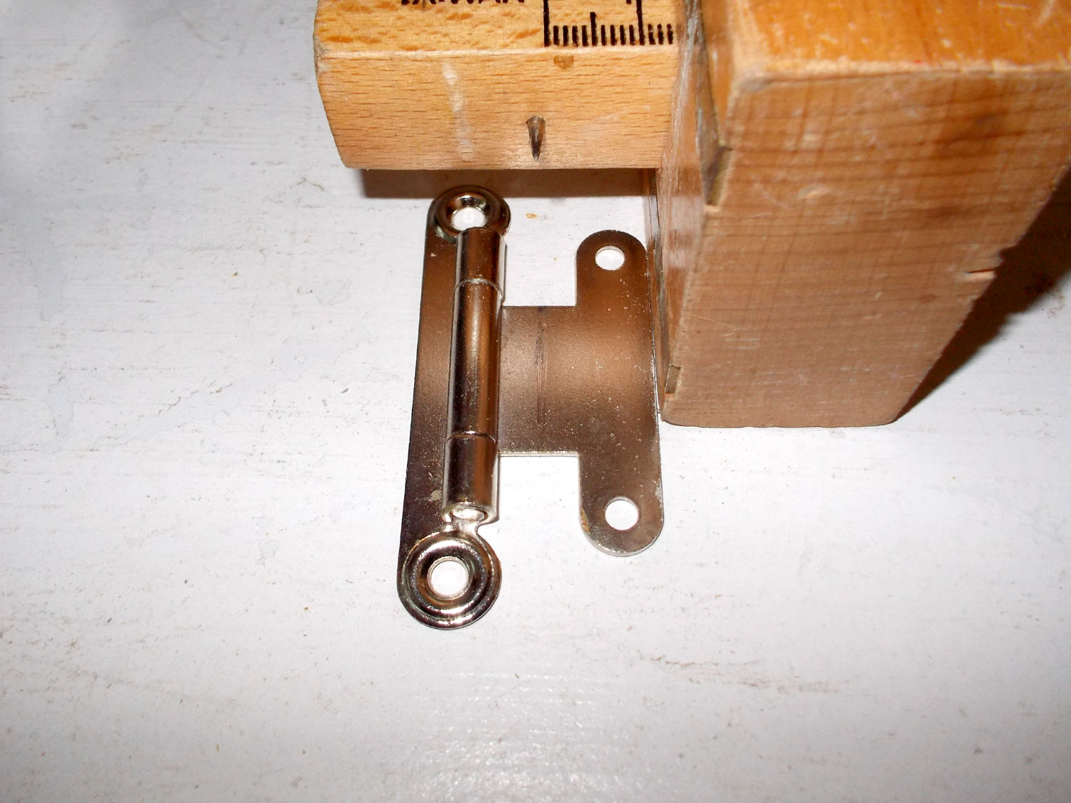
- Two pairs of hinges – I used concealed hinges mounted on the outside of the box.
- Twenty 20mm 4 gauge set screws, nuts and washers to secure hinges – and in my case two 30mm 4 gauge screws with washers and nuts.
- Two doorknobs or handles of your choice, plus their securing screws.
- Two 20mmØ fender washers for use with the doorknobs, if selected.
- Wood glue
- *Optional…two 2.5m lengths of 12x12x1.5mm aluminium extrusion cut to fit as door-front frames.
- One blister pack of twenty 5mmØ x 16mm double-ended shelf support studs (sufficient for five shelves)
- Finish of your choice.
*The aluminium door-front securing frame is optional, but it does tend to look better than simply using screws to attach the door-front to the door frame as you need far fewer screws and it means that you can quickly and easily replace the door-fronts with new if they become scuffed from writing lists on them – or you inadvertently use a permanent marker rather than the soluble erasable type designed for whiteboard use.
Note:
Many Mica stores offer a free cutting service, or might charge a very nominal fee for cutting and having the wood cut for you can save you a lot of time and energy. However, please note this: you have got to be absolutely certain of your cutting instructions. The assistant will follow your cutting instructions to the letter but if you get them wrong, it’s on you and you will not be able to return the wood. So… measure and check, then do it all over again, and even a third or fourth time and only then have the wood cut.
Method:
- First step is to measure and confirm the distance or gap between the countertop and the underside of the cupboard in the area in which you plan to keep the cupboard… there’s nothing quite like completing something, standing back to admire your handiwork – only to discover it doesn’t fit where it’s supposed to! In this case, the gap between the bottom of the fitted cupboard and the countertop is 515mm.

- I began by making the doors, first cutting the fronts to the required dimensions and confirming that they were precisely of the same dimensions.
- Then I cut the pieces for the sides and top and bottom for each door.

- When making up any woodwork or other project, the key is to measure and measure again to confirm 100% that the cuts you make will be correct.

- I usually sand the cut pieces before assembly as it saves sanding later on and into tight corners – which can be a bit of a bother.

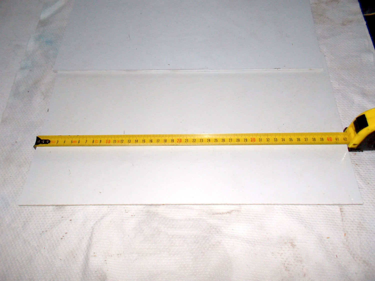
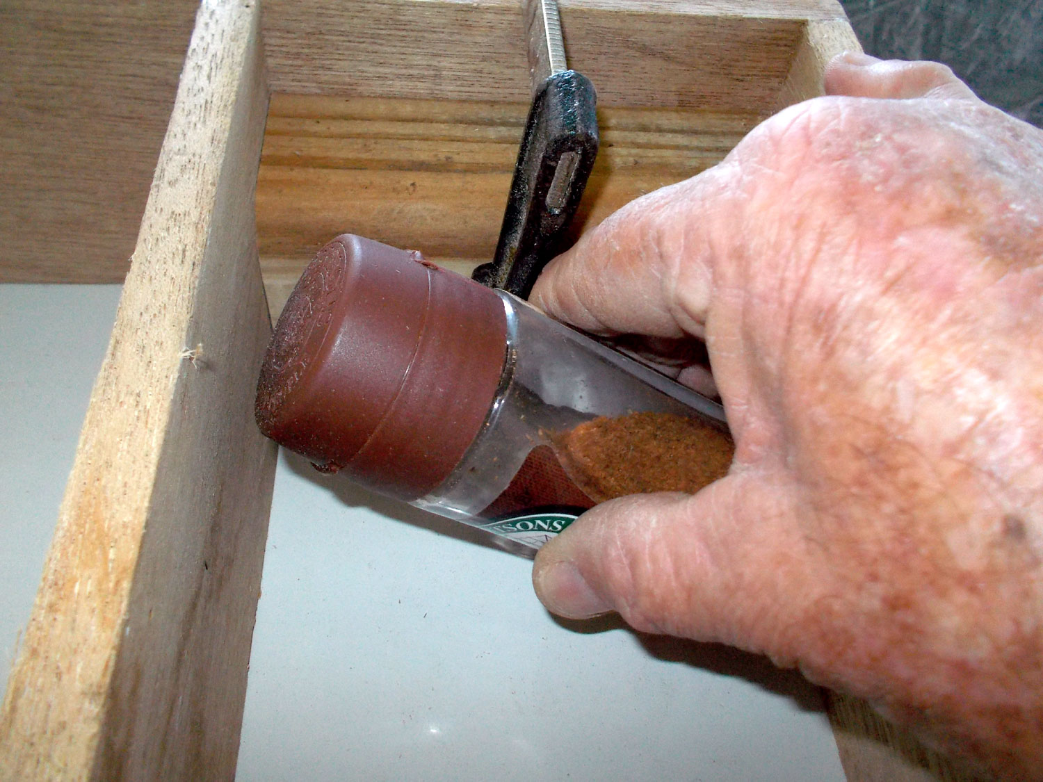
- Naturally, since you can’t write to the manufactures and ask them to kindly change their bottle sizes, you need to confirm that what you will be storing in the unit will fit. Ensure when doing so that you include the thickness of the shelves and that the bottles can be easily placed in, and removed from the spaces you have allowed for them.

- I cut a spacer from some scrap wood 12mm longer than the height of the spice bottle.

- Then I checked the bottle could be easily placed in and remove from the space. I find that cutting spacers as mentioned just above makes quick work of spacing shelves and suchlike. You have to ensure it is absolutely accurate, but then you don’t have to measure each shelf position… simply use the spacer for exactly the same shelf spacing every time.
- I used glue and a couple of panel pins on each side to secure the doors’ shelves in position.

- From there I moved on to the cupboard body, cutting the sides base and top and clamping them to a manufactured board to ensure the angles were all a perfect 90°.

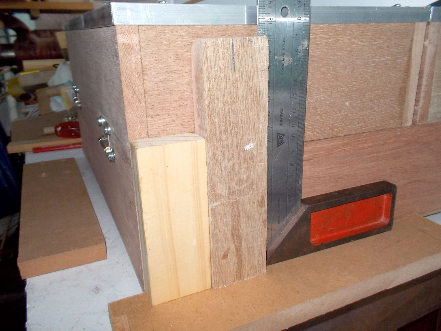
- As insurance, I used the uncut corner of a sheet of MDF as a guide to confirm the corners were square, and carpenters squares on the other corners to do the same there.

- Now for the crafty part… I wanted to make the shelves in the body adjustable for height, so I placed the sides together and used a square to mark off the various positions for the shelf height options. To keep things simple, I used the width of the square’s body as the spacing gauge. In passing, the parts of a carpenter’s square (variants of the same tool are also known as a framing square or builder’s square, for example) are as follows: The short length in the foreground is the tongue, the long arm facing away is called the body, and where they meet, is called the heel.

- Then I used a gauge to mark the shelf stud positions on the lines, set 20mm in from each side. That gives plenty of stability to the shelves.

- The 5mmØ studs are 8mm long on each side of the flange designed to prevent them being pushed in too far.

- So set against the cupboard side (12mm thick) means they can be fully seated up to the flange.

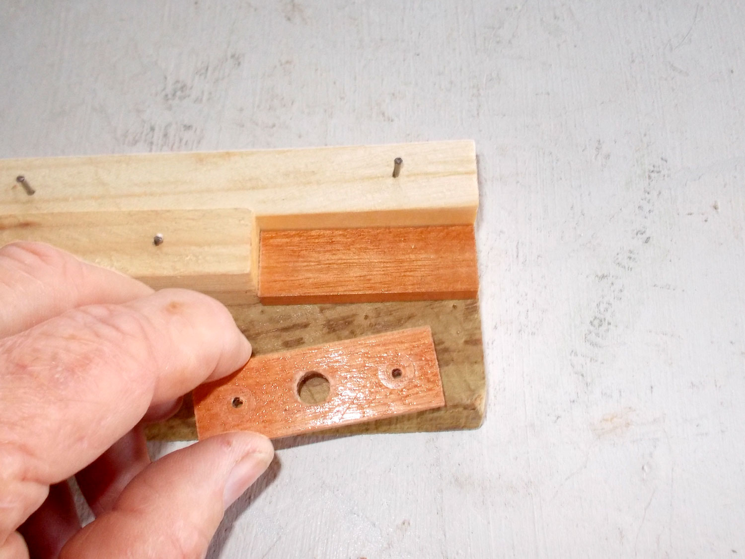
- I used the same method to mark off the shelf central support and drilled each hole right through. Then I clamped the shelf central support to the each side in turn, attached a depth stop to the drill bit to stop the drill bit going more than 8mm into each side, and placed the drill bit in the holes already drilled right through the shelf central support and drilled the holes in the cupboard sides. Ensure that you keep the shelf central support and sides in the same orientation so that the holes for the shelf studs match. Note that drilling into scrap will help ensure you get a neat result with no chipping when you drill a hole in wood.

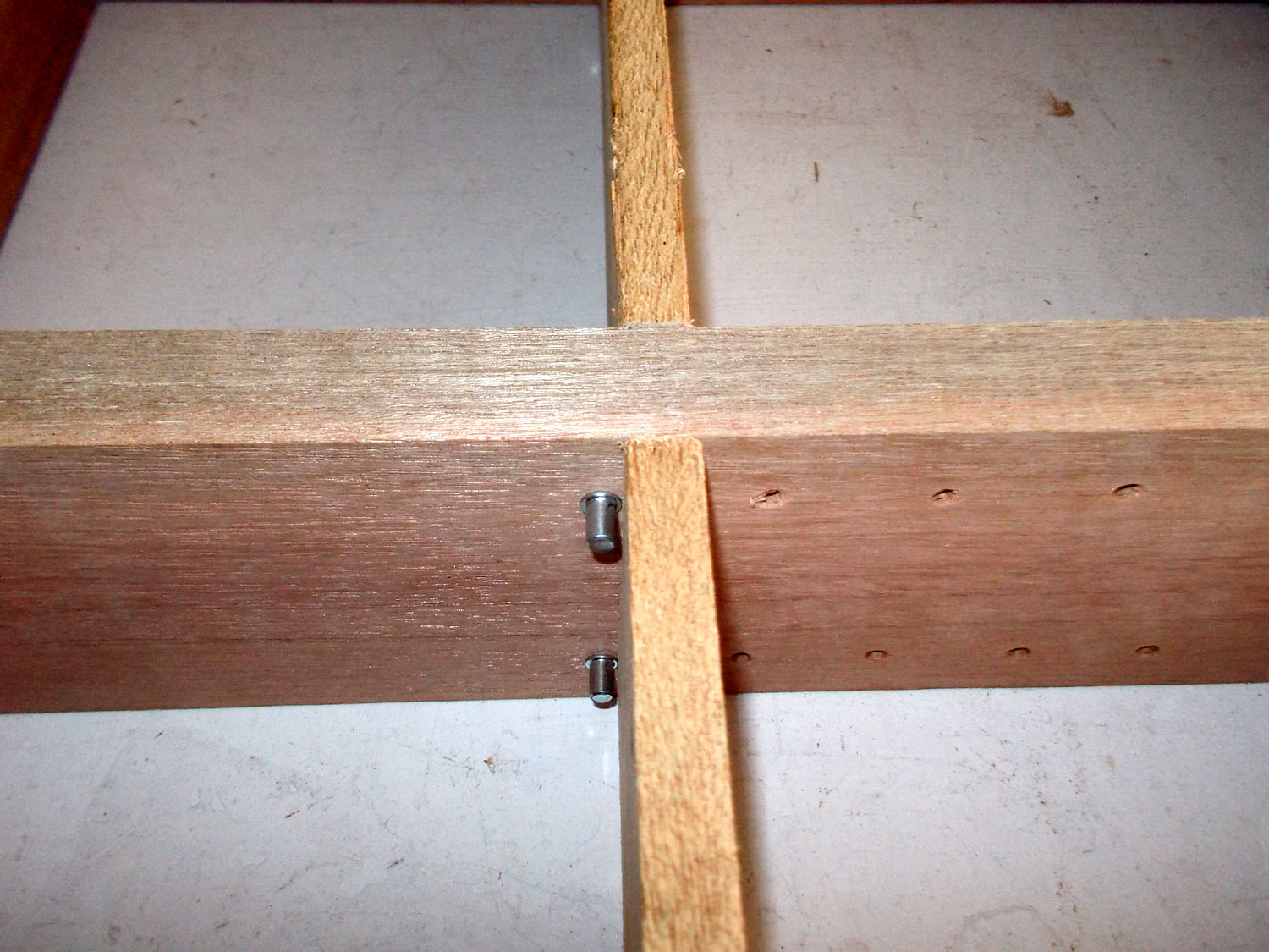
- Checking that the holes all line up.

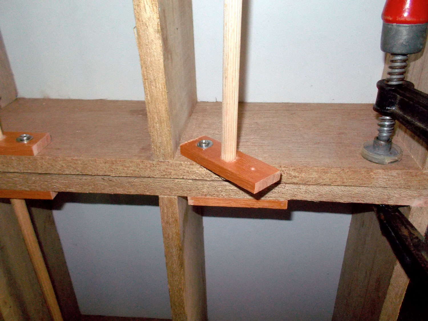
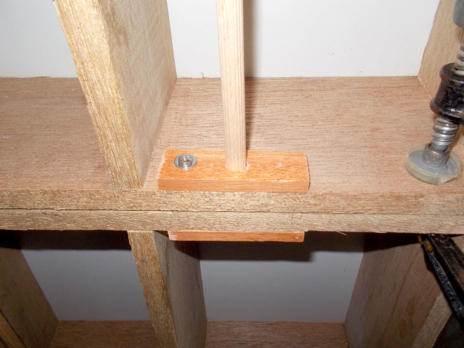
- With studs inserted into both sides of the shelf central support the shelves line up nicely.
- Here’s the body with four shelves of equal lengths.
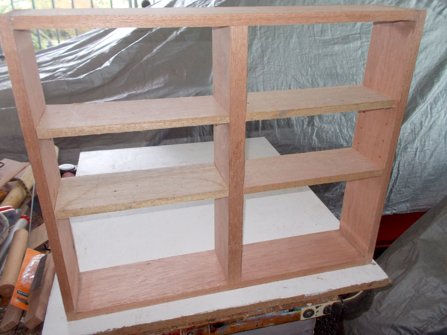
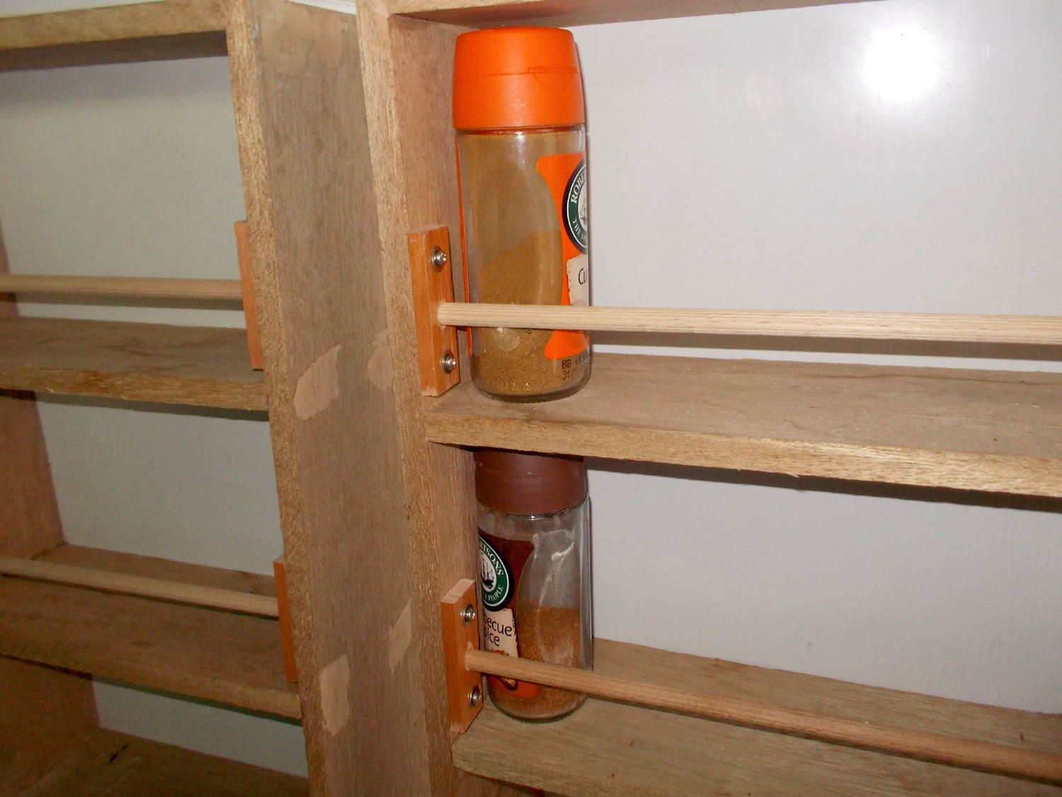
- And here, because the shelf central support can be shifted to one side or the other, two short shelves and one long one. Note how the long one is positioned between the two shorter ones. This keeps the shelf central support locked in position – though it is a very snug fit anyway.

- Round about now, I discovered that my doors had warped badly, so I had to scrap them and make new ones. To do that, I used a different technique, since the body was made and had turned out well – I had also fitted the back panel already using 16mm screws to secure it to the body… I measured up and cut the new four sides and clamped the outer ones to the body, using the shelves as temporary blocks to keep the door sides precisely aligned with the body sides. Then I positioned the two inner door sides with four washers between them to act as spacers, and cut the two tops and two bases to fit.

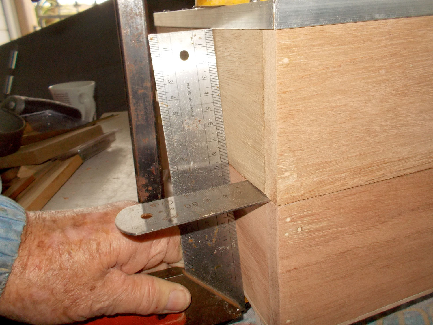
- Then I clamped the whole lot together as shown as a dry fit to confirm everything was shipshape.

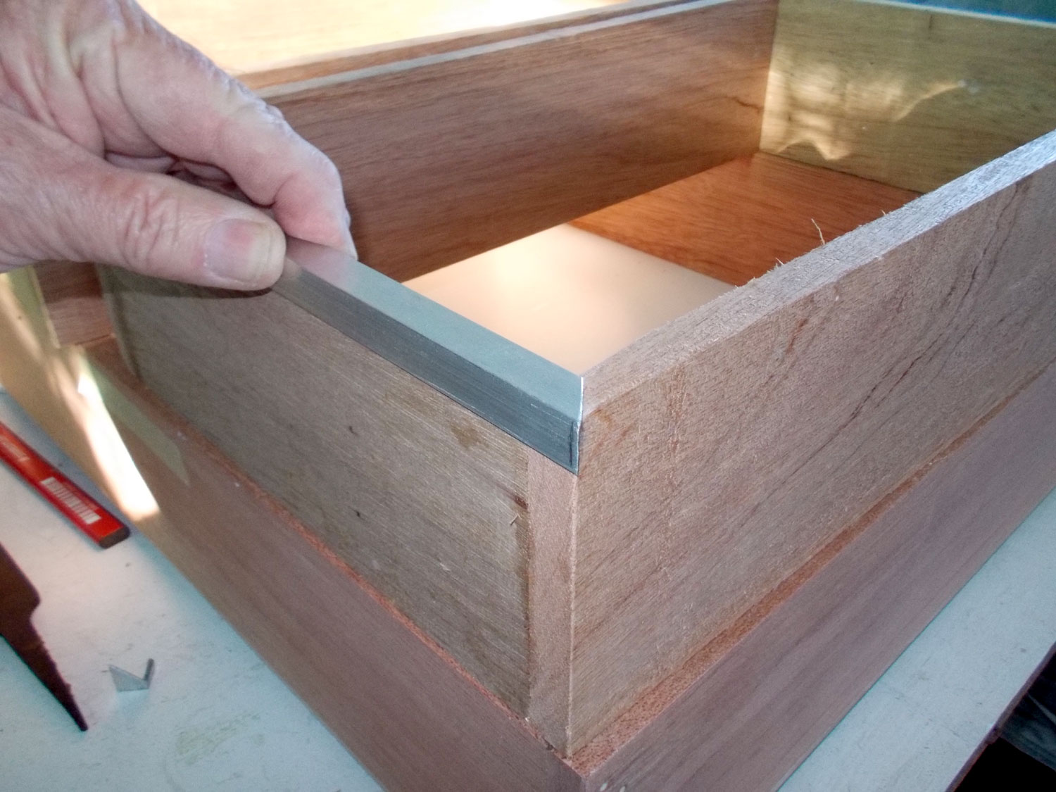
- I used a steel rule to ensure everything had lined up properly.
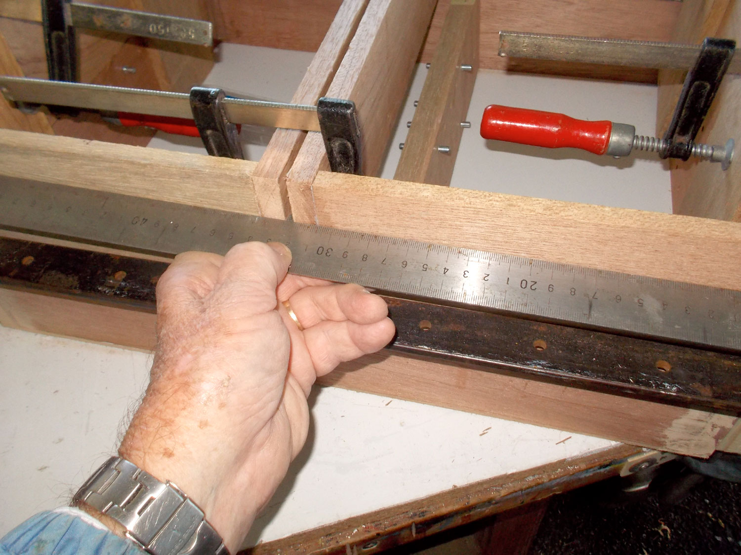
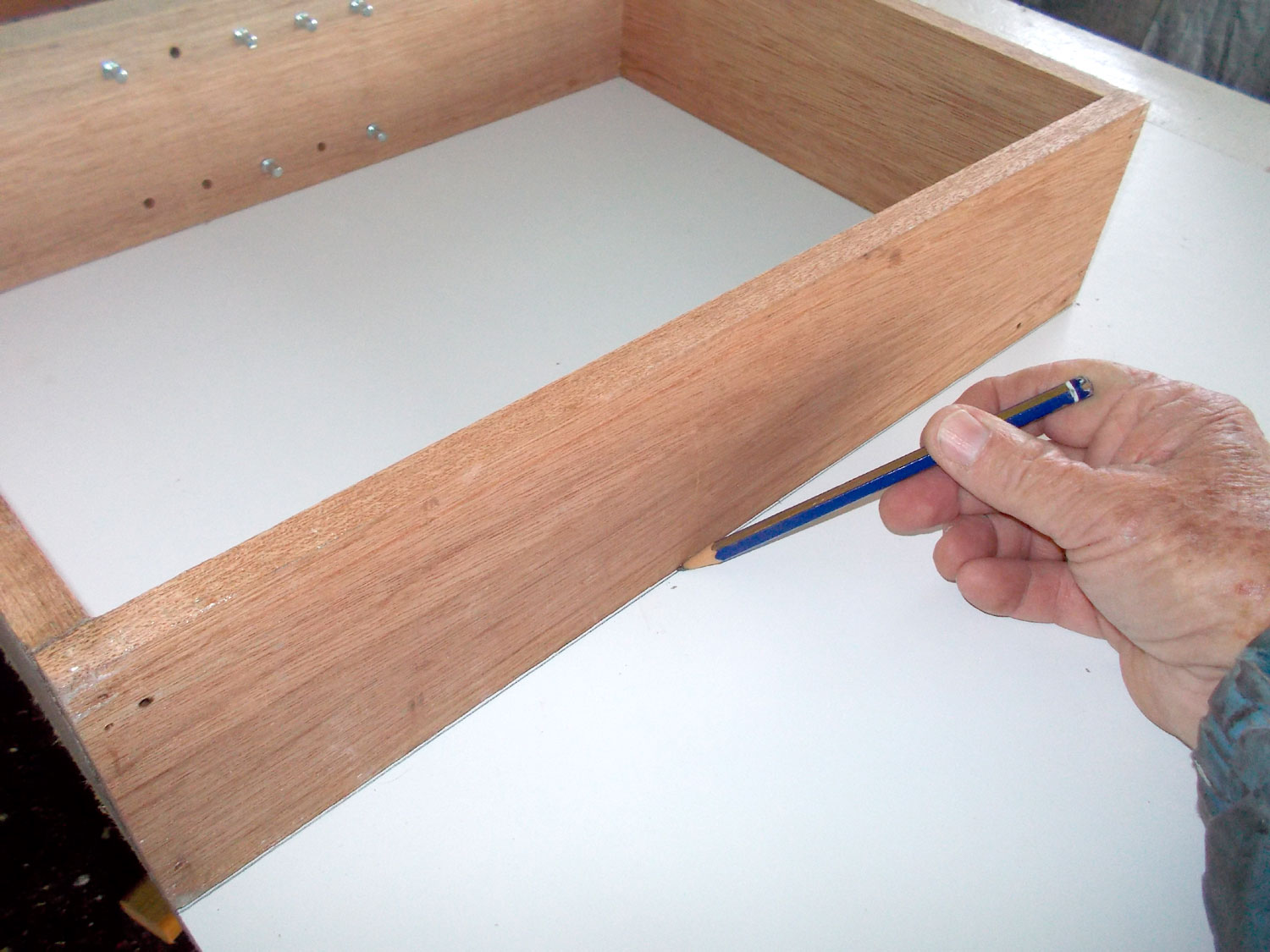
- Once satisfied with the fit, I unclamped everything, applied glue to the door joins and clamped everything back together again, while the glue cured. Once it had, I could then place the door frames on the (new, replacement) sheet for the fronts and mark off the cut lines.
- When cutting board, plastic, Perspex or other thinner materials using a utility knife, always put the rule – here you will I have clamped it along the cut line – on the INNER edge of what will be your workpiece. This ensures that if your knife goes rogue, it will do so away from your workpiece – and not over it.

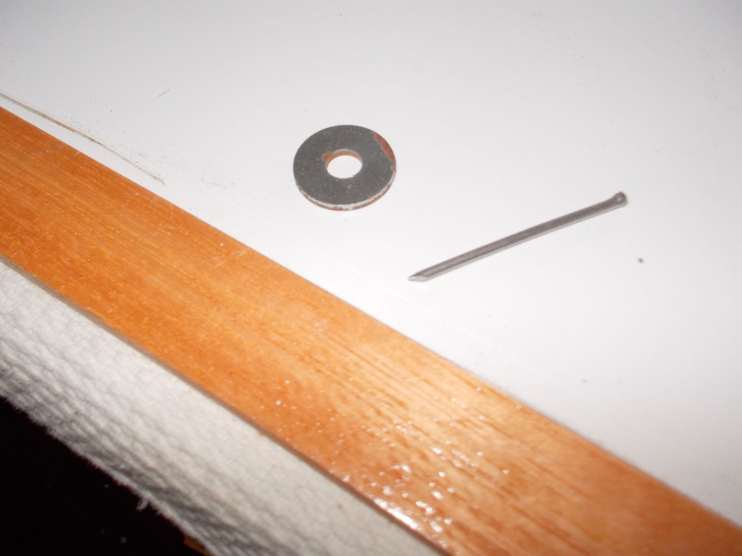
- As the door sides are 12mm thick, I decided to use a suitable washer to mark the drilling line in what would be the INNER surface of the door fronts… the washer disc is 5mm wide as shown here – ideal as a measure.

- Then it was just a case of placing a panel in the washer and holding the door front hard up against a straight piece of wood, and then pulling the pin along the edge… the washer kept turning, the panel pin kept scratching a line – and I ended up with a perfect drilling line along the edge of the door front. The line is just visible in the upper left quadrant of the image.
- To make the line more visible, I scored over it lightly with pencil and then drilled the holes for the securing screws.

- This shows how the screw holes line up when the doors are closed.

- I attached the front to the two sides and then slipped the top and base into position, using glue to secure the join.

- I added two panel pins per join to reinforce them. I countersunk the heads of each a little below the surface and filled the holes with filler – later sanded down to flush with the wood’s surface.
- Then I got to thinking that to secure the door fronts to the door frames would require quite a few screws. So I decided on a new angle… with 12 x 12 x 1.5mm aluminium angled edging. It would look better and require fewer screws to secure the front to the frame, and hence be easier to remove if the front ever had to be replaced.
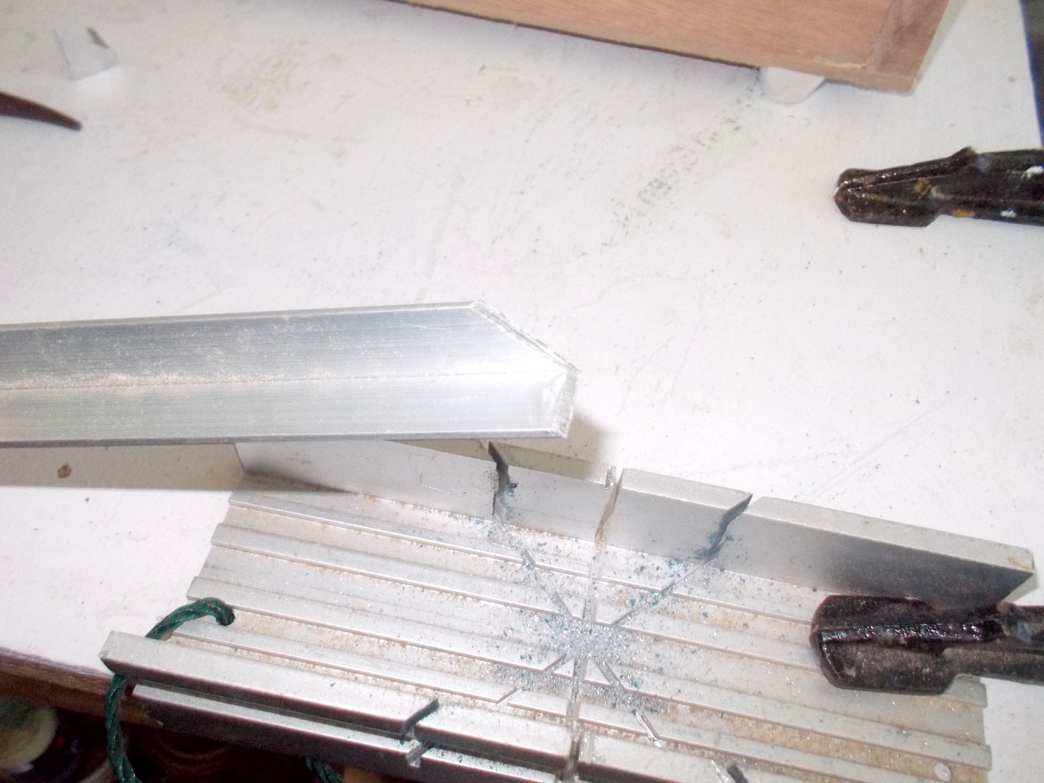
- I cut and fitted each edging piece one at a time; I didn’t want to cut all eight pieces at once only to discover I could not get a good fit where they meet at the corners.
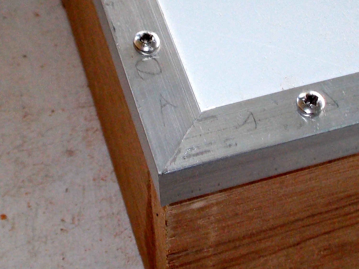
- I dry fitted the pieces beforehand, and once satisfied with my corners, only then did I use the gauge to mark the drilling line for the 16mm 4 gauge pan head securing screws. The ones closest to the corners are 30mm in, and the others are spaced for a neat result. The top and bottom lengths are secured with three screws each, and the side pieces with four screws each.

- To get corners like this required a large amount of sizes and filing, sizing and filing… until the desired result was achieved.
- Then I fitted the replacement shelves as before, but note the use of the two squares to ensure the shelves were true in all axes.

- Again, a couple of panel pins reinforced the glued join.

- Now for the shelf contents retainers… when you open the doors you don’t want the contents to fall out and if they are glass – shatter. The retainers in this case are 8mmØ dowels rods, held in place with small mounting blocks. So I cut some leftovers – in this case 6 x 19mm moulding – of a previous project each to 55mm and in one drilled VERY accurately, the 8mmØ hole for the dowel, and two 2mm pilot holes for the securing screws. I then made up a very simple jig.
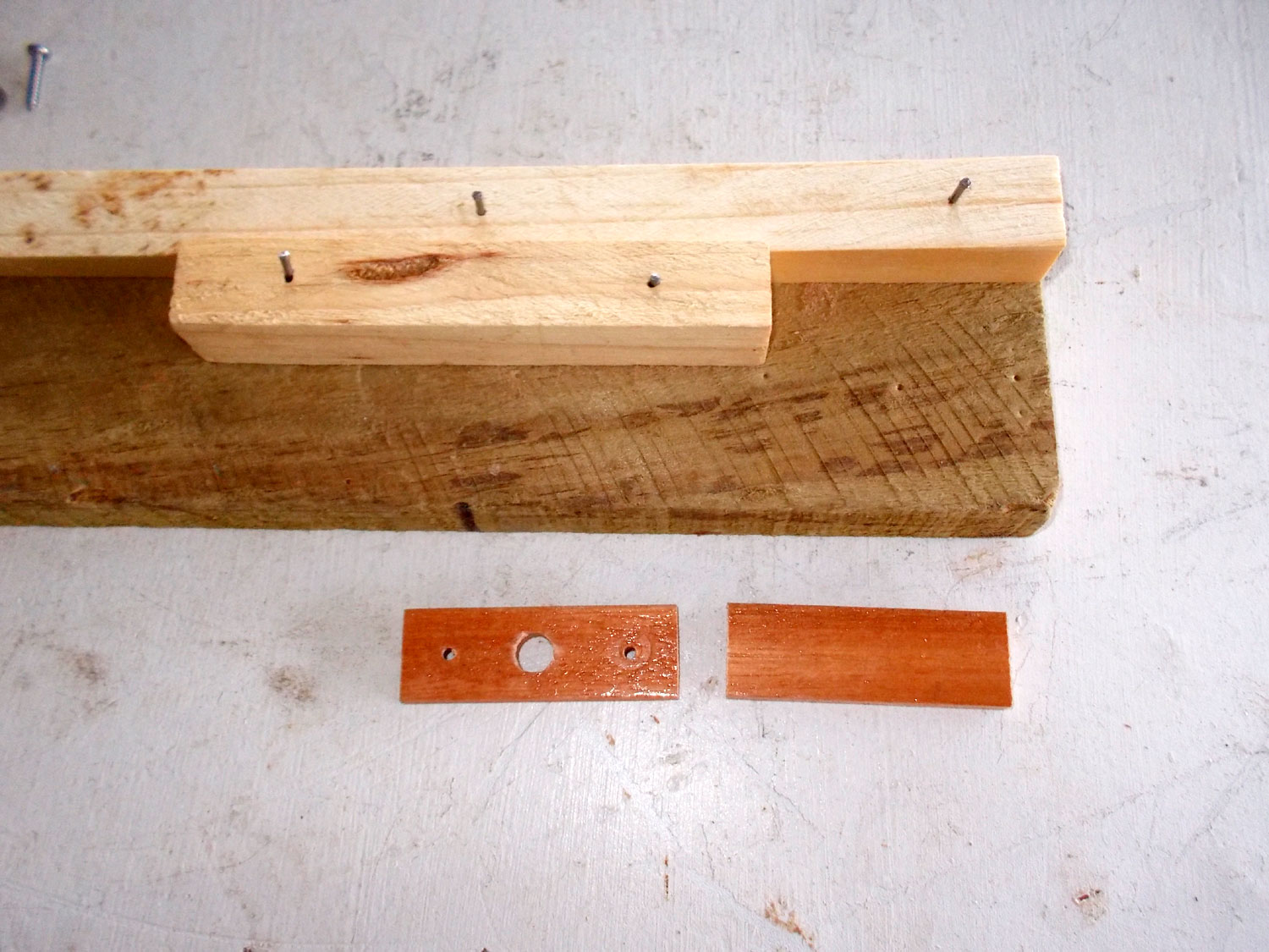
- Placing the drilled block over its mate, I was able to drill the holes in all the blocks very accurately.
- Here are eight of them – four left to go.

- Now I secured three in each door side, 6mm up from the shelf – note the left over 6 x 19mm piece being used as a positioner. The reason for mounting the block with a gap between itself and the shelf will become apparent just below.

- Here’s the first of the blocks secured in position.

- I used a junior hacksaw to cut the dowel rods to fit between the sides of the doors.

- Here’s the reason for that gap… with the second block secured with just one screws, one end of the dowel is slipped into this block, and slightly below the bottom surface. This allows the other end of the dowel rod to be inserted into the block above.
- Now the block is pushed into position and the second screw secures it, locking the dowel rod in position. The beauty of this method of attachment is that if a dowel rod ever break, reversing the procedure allows for its easy replacement.
- The dowel rods in position and doing what they are meant to do.
- Now to secure the doors to the body… I clamped them together as shown – note the use of the steel rule to give a separation of about 1mm between body and door when the latter is closed.

- This will be the top of the cupboard – and door and body are flush.
- This will be the bottom of the cupboard – and the 2mm gap is evident. The reason for the gap? Simple! It is to put a little space between the cupboard feet and the doors.

- Now for the hinges… these are named concealed hinges, but I used them in a very different – and very visible (unconcealed) way… first I marked their body centre line. Note that this does not correspond with the fulcrum, but with the hinge body. The reason for this is because I wanted to ensure that there would be sufficient wood on both the door and the body for the securing screws
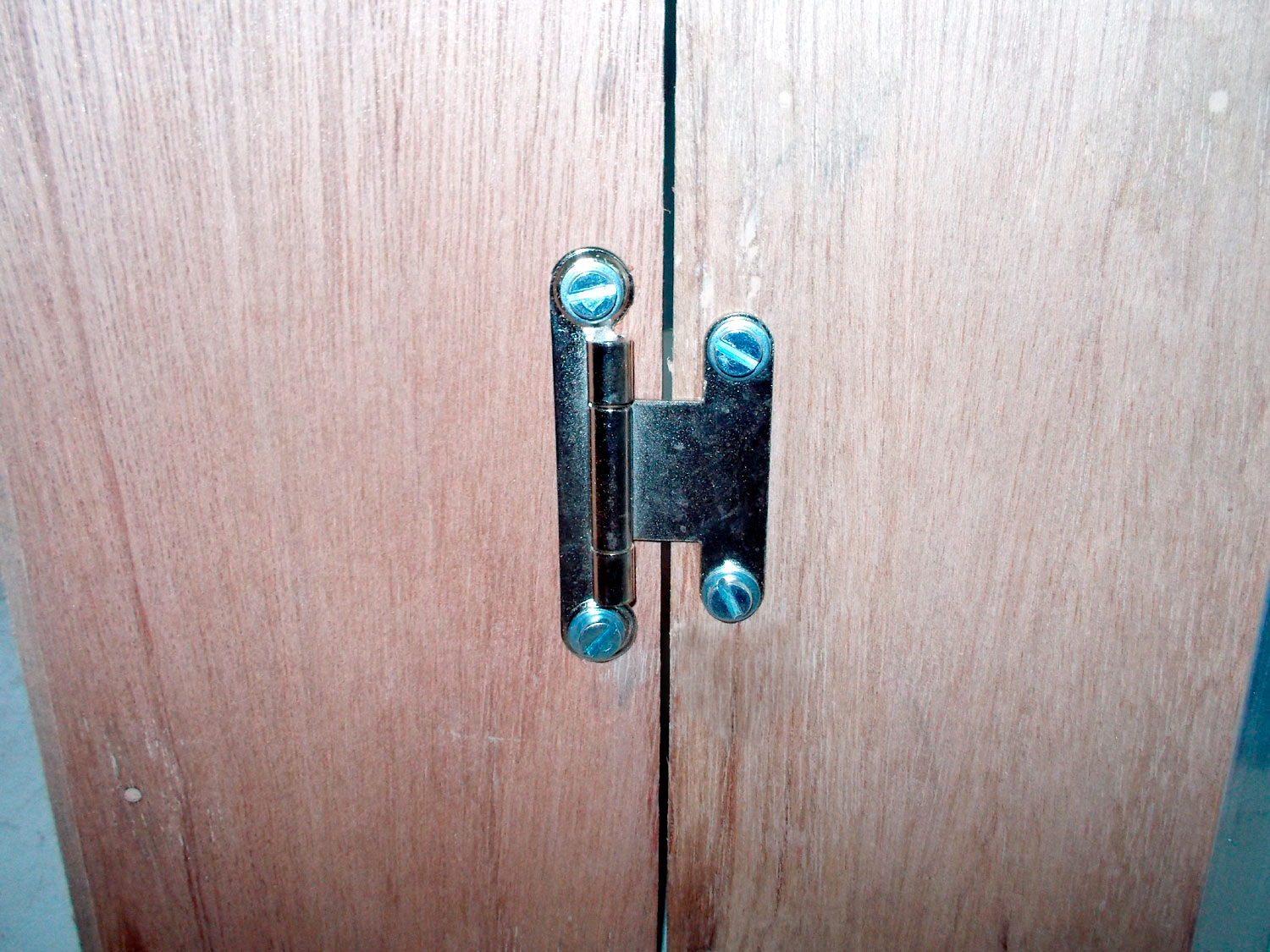
- Like this… there is quite a bit of wood on the left. As a final finishing touch I aligned all the screw slots vertically… not pointing every which way as shown here.
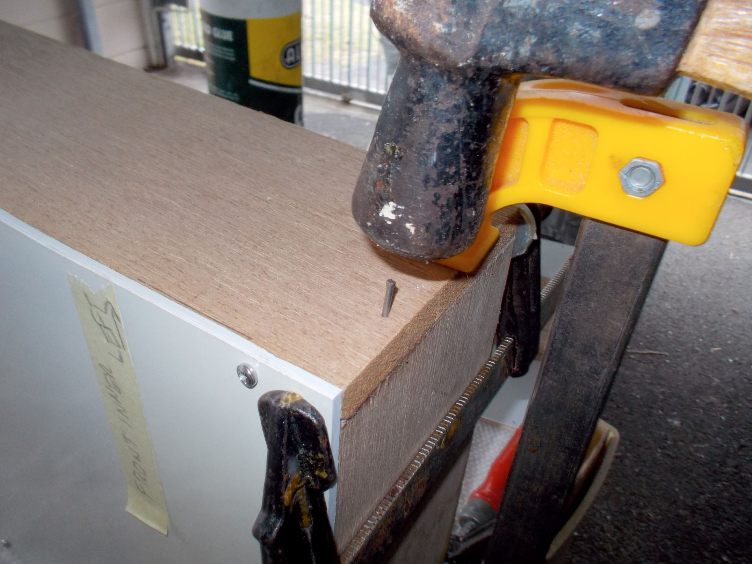
- Here I made a bit of a blupse… I managed to position the top hinges 20mm from the top of the body and doors, but I positioned the lower hinges 70mm up from the base of the body – which ended up with one hinge securing screw passing right through the dowel securing block. So here I had to use a 30mm screw in each case…

- Like this. If I had been just a few millimetres lower, I would have gone straight into the block securing screw. By the way, the dowel can still be easily replaced if necessary as the block securing the other end can be swung out as mentioned a few images above showing the blocks being fixed in position.

- Now for the feet. I used an offcut from a previous project cut in half and bevelled the leading ends.
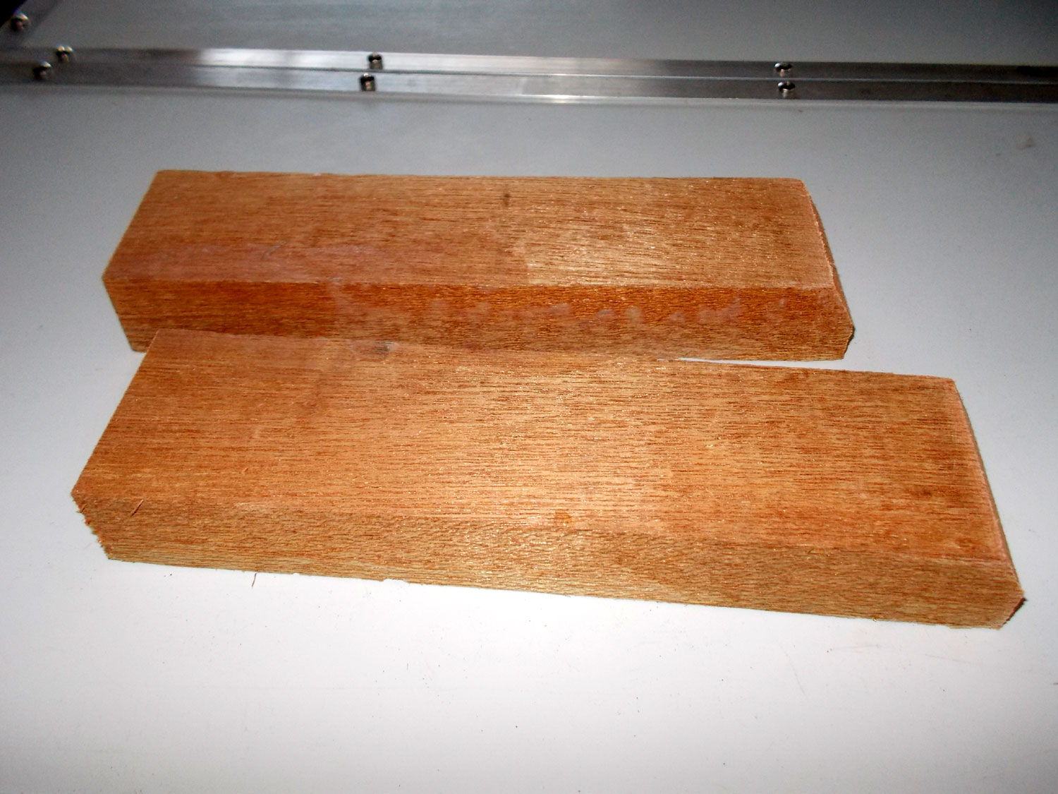
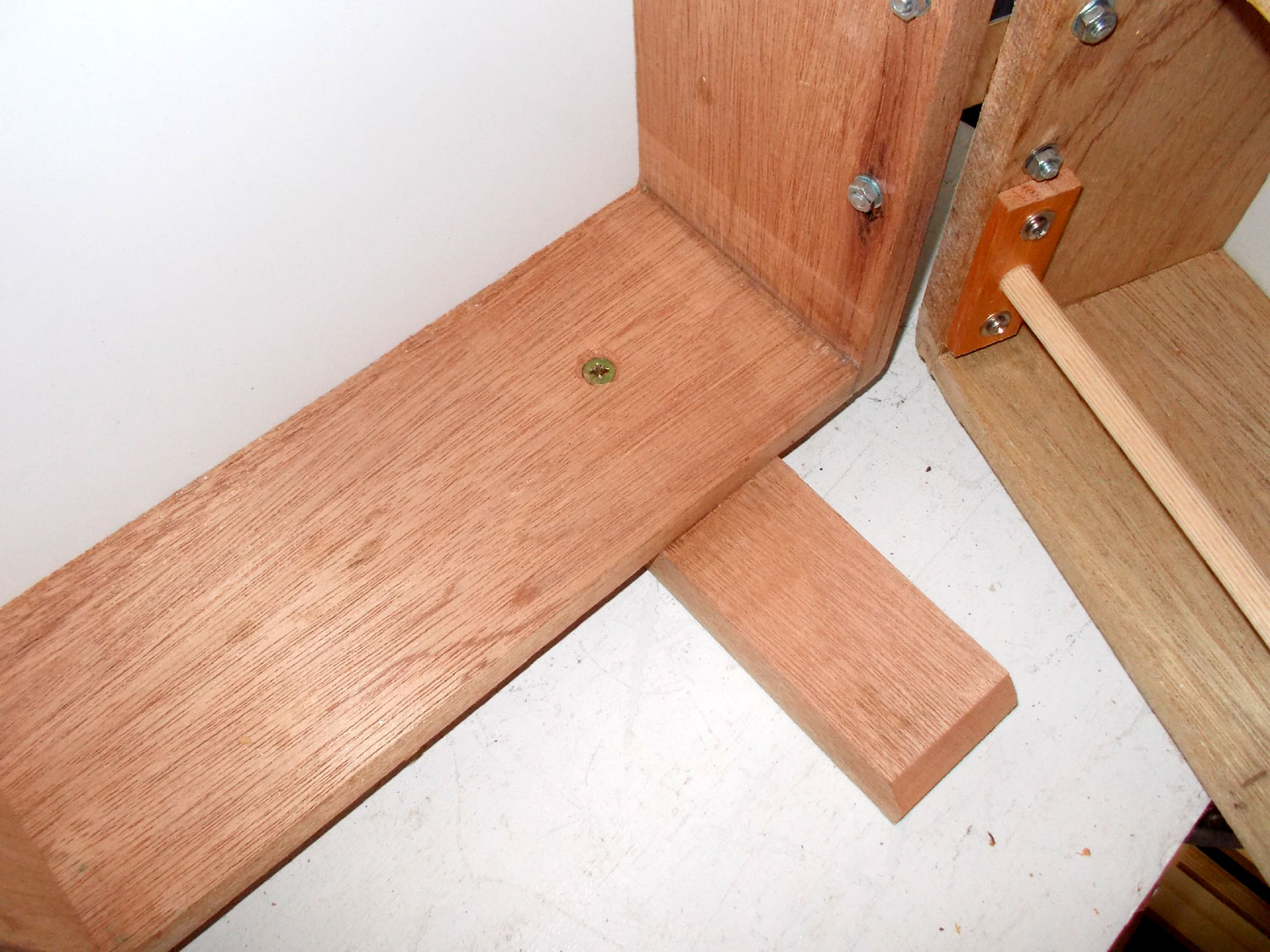
- They were glued into position 44mm in from the side of the body and about 16mm in from the back of the body to give a little more of the foot to the front of the cupboard… putting its best foot forward, so to speak.
- This is optional, as the glue alone make a very secure join, but for added security, I drove a 30mm screw – countersunk into the base of the cupboard body – into the screw to really secure the join. Of course I took care to ensure that no screw tip penetrated the bottom surface of the foot – as that would have resulted in the countertop being scratched.
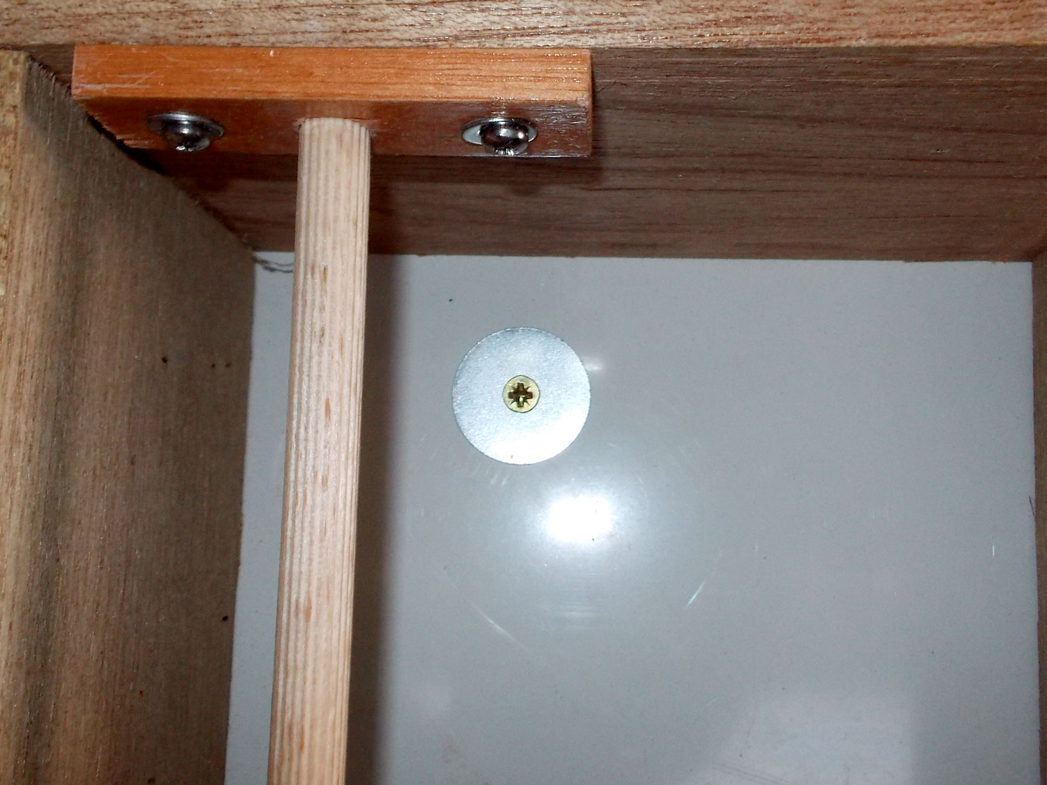
- Now for the catches. Originally I was going to use magnetic catches, but then decided to use spring-loaded roller catches as shown here, with their mounting blocks. They have to be mounted on the underside of the body as the shelf central support is movable and the catches cannot be mounted on it.

- I used three 16mm screws and glue to secure the mounting blocks to the undersides of the door bases.

- Then I secured the shaped striker to their blocks.

- Then I clipped the catches on to them and used suitable offcuts to line them up and secured them with their screws.

- Now for the doorknobs. Again, I changed my mind. I was going to use drawer handles, but I thought they would look a bit large for the doors, so I decided on oak doorknobs instead. I used a soluble marker to mark the position of the doorknobs at the bottom of the door. This is for two reasons… they are close to the catches and so there is little tendency for the cupboard to be pulled over forward if they were mounted at the top or even at the midpoint of the doors. Secondly, they leave more writing space where you are likely to be writing, right?
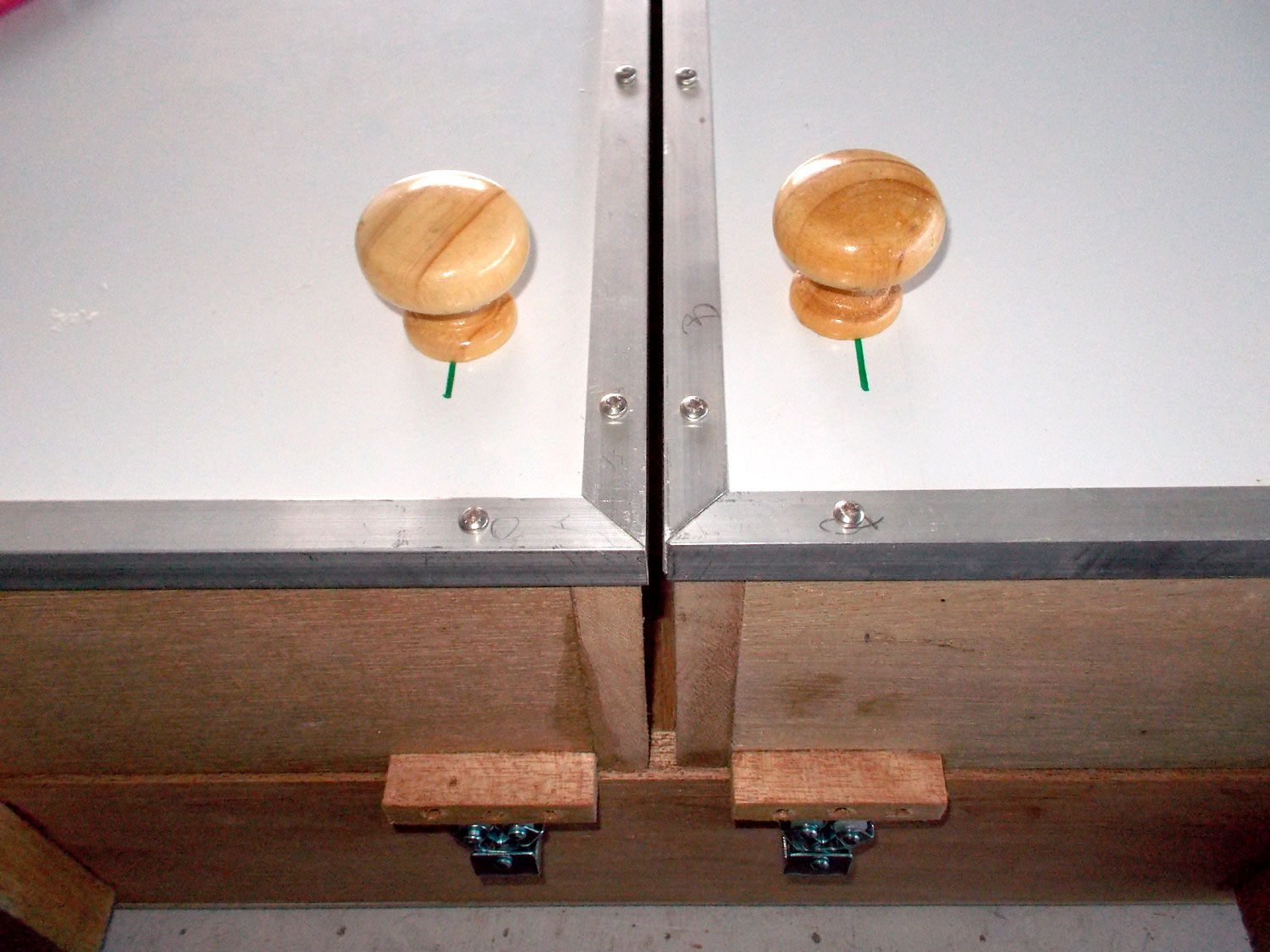
- Happy with the position, I drilled the single hole required for each and attached them to the doors.

- Boxing clever, however, I used a 20mmØ fender washer with each to increase the load area when the doors are opened… simply using a screw might have seen it being pulled through the door front. Unlikely I know, but rather one precaution too many than one too few.
- While I was about it, I decided to make up a template for drilling extra shelf positions if required. I clamped this piece of MDF to the shelf central support, and drilled through four of its shelf stud holes. Then it’s simply a case of popping a stud into two of the holes and popping them in turn into the top empty holes in the shelf central support and body sides. Then you set the drill stop to the correct depth.

- And you drill the new holes.

- As a final finishing touch, I attached four 19mm rubber buffers to the back of the cupboard so that it would not slam into any wall tiles and possibly damage them. I sanded down the one side as shown here so that it would not show when the cupboard is views from the front.


Those versatile hinges…
This illustration shows the beauty of using the hinges as I have done in this project… you can easily set the doors if they do not line up precisely… adding washes shown in red to the door flap of the hinge will move the door inwards towards its mate. Adding washers shown in blue to the body flap of the hinge will more the door away from its mate.

Those versatile shelves…
This just shows how the two longer shelves on the left lock the shelf central support in position. In the case of the unit shown here, the fit is very tight (but not so tight that it could break anything in the body) so it is unlikely to move anyway, but rather safe than sorry.

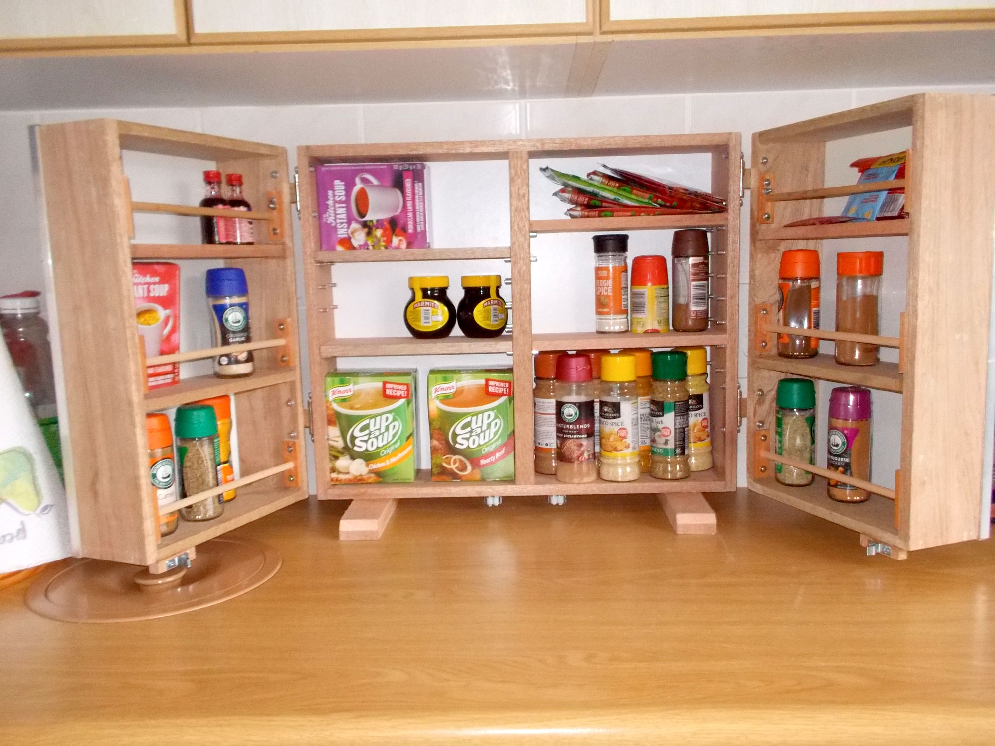
Here’s the cupboard closed with the door front acting the role of very handy noticeboards for what needs to be bought or done.
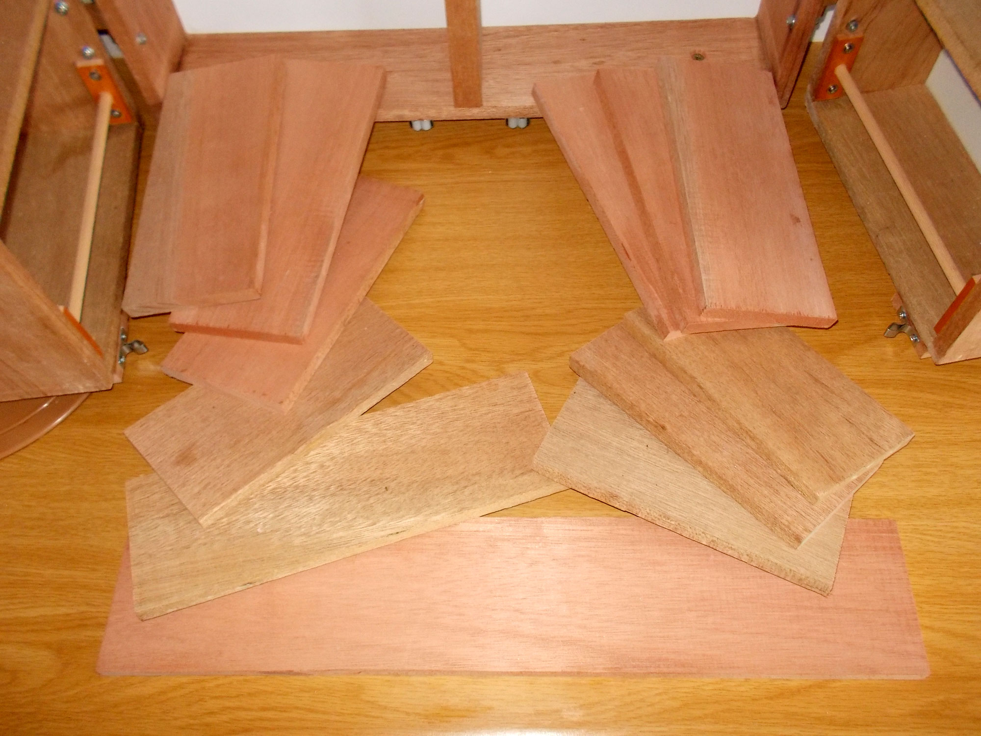
Here is just a selection – there are many more possible – of different shelf lengths that allow for great versatility in the cupboard’s storage role.

Here’s the cupboard without the shelf central support fitted and one long shelf across the entire width of the body. Naturally, you can have more if you wish.
With the shelf central support fitted, we have four shelves of equal length at various heights.

And here is it with the two shelves of equal length and one far longer one.
Project guide
Skill level: 3
Estimated time: a week or so
Cost: R1000 depending on how many shelf combinations you decide upon and whether you also choose to go with the aluminium door surrounds.
Assistant: No
Tools required:
Drill/driver, jigsaw or circular saw; sander; hacksaw and mitre box.
Panel:
These materials are available at Selected Mica Stores. To find your closest Mica and whether or not they stock the items required, please go to www.mica.co.za, find your store and call them. If your local Mica does not stock exactly what you need they will be able to order it for you or suggest an alternative product or a reputable source.