06 September 2019

MICA – HOW TO USE A MULTIMETER
First of all, there is NO substitute for reading the instrument’s instructions first, and understanding them, before using any multimeter.
So, let’s take a look at this very useful instrument and how to use it.
Different readouts
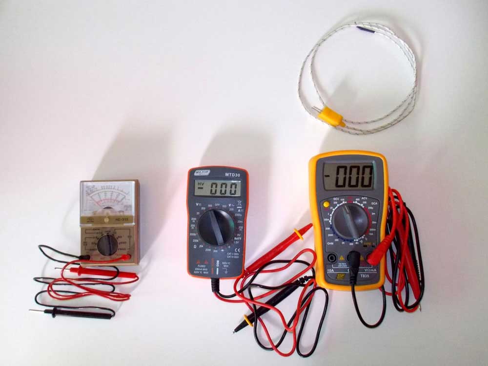
Multimeters (also known as volt-ohm meters) are used to test voltages (volts),
current (amps) and resistance [earthing] (ohms). The readout is either digital
(LED) or analogue (needle) and the selector dial on either type allows you to
select the various functions, and ranges within those functions. For example,
the AC voltage function might offer a choice of 10, 50, 250 and 500 volts.
Note that in the picture above, the device on the right has three ports for the probes. We refer to the ports again in this article. The multimeter in the centre is the one we used in this feature to show how the device is used. Also note that the device on the right has a third lead – the coiled one above it with the yellow plug – that allows the user to take temperatures – the end of the lead has a temperature sensor.
There are essentially two readout types – analogue, which employs a needle dial, and digital, which as the name suggests, displays results on a digital readout. The advantage of the latter over the former is that the digital readout gives the user a very precise, easily readable result in numbers. The analogue version, as it uses a needle, means the user sometimes has to estimate by eye exactly what the needle is reading on the dial.
However, note that before using an analogue version, you need to ensure that the instrument is zeroed – that the needle with the instrument off, is reading zero. To do that, you simply turn the adjustment screw, usually situated just below the dial, clockwise (needle moves right) or counter-clockwise (needle moves left), and you will see the needle will move accordingly. Note that the amount the screw needs to be turned is very little… usually no more than a quarter turn or so.
Carefully and gently is the way to go!


Types of dials and what the symbols mean
Different versions of multimeters have different dials according to their brand and their capabilities. As you can see from these images, the two digital multimeters have more functions than the analogue version, but essentially, all three have the same basic range of uses.
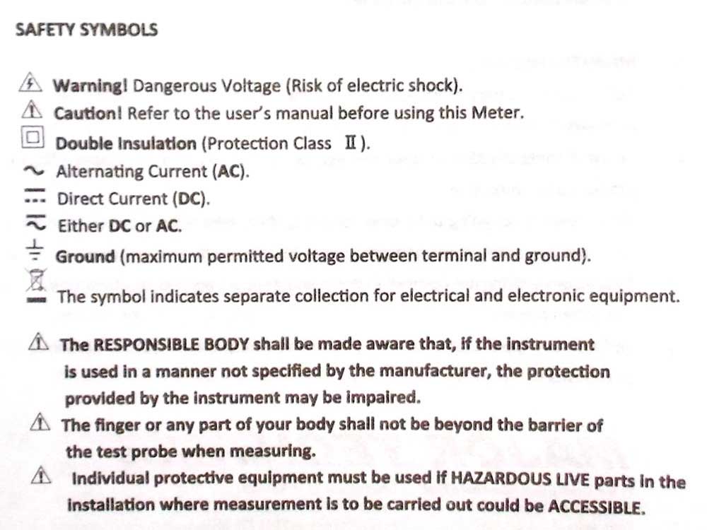
Symbols
The next objective is to ensure that you understand the symbols on the dial. Reading
from the top left of the dial and reading clockwise:
- Direct Current Voltage (DCV): Sometimes it will be denoted with a V▬. This setting is used to measure direct current (DC) voltage, for example when checking a battery.
- Direct or alternating voltages (V
 ): When the symbol V is accompanied by a flat bar above three dots, as on this dial, it means that when set to this position, the instrument will measure direct or alternating voltages.
- Direct or alternating voltages (V
- Alternating Current Voltage (ACV): Sometimes it will be denoted with a V~. This setting is used to measure the voltage from alternating current sources, which is the type of electricity that is used in your home and business.
- Resistance (Ω): This measures how much resistance there is in the circuit. The lower the number, he easier it is for the current to flow through the material, and vice versa. Hence, when it shows 000, it is easy for current to flow through. When it shows 1, there is no path for the current to flow between the two points being checked. When it shows, for example, 007, the current can flow easily, but there is more resistance to its flow than when the reading is 004 for example.
- Continuity (
 ): Rather as what happens when resistance is checked, a small amount of current is sent through the circuit to test whether or not it is complete. If it did, the circuit is complete. If not, the circuit is not complete so there is a break or disconnect somewhere in it.
 - Direct Current Amperage (DCA): Similar to DCV, but instead of giving you a voltage reading, it will tell you the amperage.
- Direct or alternating amperage (A ): When the symbol A is accompanied by a flat bar above three dots, as on this dial, it means that when set to this position, the instrument will measure direct or alternating amperages.
- Direct or alternating amperage (A
- BATT: Your multimeter might also have a dedicated setting for testing the amperage of AA, AAA, and 9V batteries. On this multimeter this is indicated by the 9V BATT 1.5V setting on the dial – see the lower right-hand quadrant on the dial
Earth/Ground ( ![]() ): This is the symbol you will find next to the large top pin on an electric plug. The green/yellow-striped wire from this pin will be connected to the chassis of a kitchen appliance, for example, and is there to ensure that if a fault occurs and power goes from where it should in the appliance to any part of the appliance connected to the chassis, the earth leakage will be triggered on your electricity distribution board and cut off the power.
): This is the symbol you will find next to the large top pin on an electric plug. The green/yellow-striped wire from this pin will be connected to the chassis of a kitchen appliance, for example, and is there to ensure that if a fault occurs and power goes from where it should in the appliance to any part of the appliance connected to the chassis, the earth leakage will be triggered on your electricity distribution board and cut off the power.


Zeroing an analogue multimeter
As you
can see in the one picture, the needle is not on zero, and if the device is used
in this condition, it will give an inaccurate result.
So with a very gentle turn of the zeroing screw, about a quarter turn counter-clockwise, the instrument is zeroed and work can begin.
How to use a multimeter
For
starters, let’s go over some of the different parts of a multimeter. At the
very basic level you have the device itself, along with two insulated probes,
black and red, on cables.
The multimeter itself has a display at the top, which gives you your readout, and below that a selector that you rotate to select a specific setting. Each setting may also have different number values, which are there to measure different strengths of voltages, resistances, and amps. So if you have your multimeter set to 500 in the V~ section, the multimeter will measure alternating voltages up to 500V.
Your multimeter will also have two or three ports for plugging in the probes.
The COM port stands for “Common”, and only the black probe is plugged into this port.
- The VΩmA (voltage, resistance, and current [in milliamps]) port is sometimes denoted as mAVΩ ([current [in milliamps], voltage and resistance). This is where the red probe will plug into if you’re measuring voltage, resistance, continuity, and current less than 200mA.
- The 10ADC port (sometimes denoted as just 10A) is used whenever you’re measuring current that’s more than 200mA. If you’re not sure of the current draw, start with this port, using the red probe. On the other hand, you would not use this port at all if you’re measuring anything other than current.
Warning: If you’re measuring anything with a current higher than 200mA, plug the red probe into the 10A port, rather than the 200mA port. Otherwise you could blow the fuse that’s inside of the multimeter or destroy the device itself.
A note
about fuses
Your
multimeter is fitted with a fuse to protect it should you use an incorrect
setting to take a measurement, such as a voltage or amperage. When you replace
the fuse you MUST replace it with a fuse of EXACTLY the same rating. Never
replace it with a fuse with a higher rating as you could be risking the
destruction of the device – or injury to the user.
A note
about settings
When
measuring voltages or amperages, whether direct or alternating, ALWAYS set the
selector to the highest setting first and then work back down towards the lower
settings until you obtain an accurate readout.
Right, now let’s get started actually using a multimeter. We’re sticking to simple tasks you’re most likely to use it for, such as measuring the voltage of torch battery, a car battery, whether an extension cord is sound or not and whether a toaster is in good order. Before using your multimeter, refer to the Disclaimer/Advisory at the foot of this article, and make sure you read and understand the instructions that came with the device.
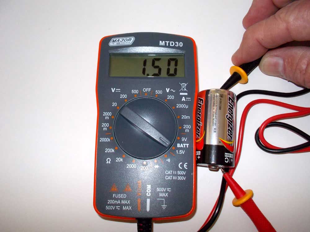
Testing a torch battery
The issue with torch batteries is that they are rather like a chain in that once one fails, no electricity can pass and the torch dies. It often means that only one battery has died, but if you cannot test each battery, you end up throwing out the lot.
This is where a multimeter will save you money. You can check each battery, find the dead one, and replace only that one.
Begin by setting your multimeter dial to 1.5 in the BATT sector and put the black probe on the battery base (–) and red one on the positive (+) top. This battery is good as it is producing 1.5V. If it gave a reading of 1.2V or less, then you need to replace it.
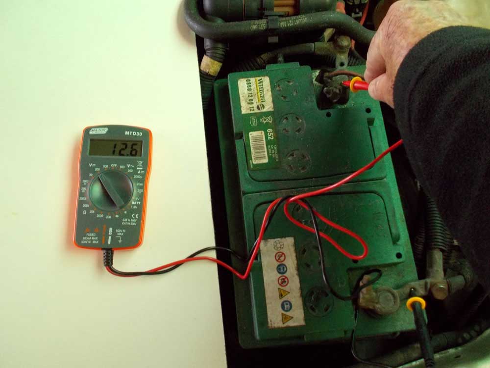
Car battery test
Here’s essentially the same test, but this time on a car battery. Note that the
selector is now set to 200 in the V sector and the readout shows 12.6V. A
reading between 12.4-12.7V means the battery is fine. Lower than 12.4V means
you need to perhaps look at replacing it. DO NOT USE THE BATT position when checking a car battery – you will probably blow
the multimeter’s fuse.
As a general rule:
Car batteries provide 12.6V DC (direct current) through six cells, producing 2.1V each.
~12.6V: fully charged
~12.4V: 75% charge
~12.2V: 50%
~12V: 25%
11.9V and below: effectively zero charge so you either need to recharge the battery or replace it.
You can also test your car’s alternator. Turn the engine on and rev it, the voltage should increase to around 14V. If it does not, you might have a faulty alternator and need to take your vehicle to an auto-electrician for checking.


Testing continuity
To test the continuity of a circuit, first set the selector dial to the
continuity test setting or the audio setting – see the close-up of the selector
dial above. All we have done here is touch the two probes together and you can
see that when they touch there is a continuous circuit and the readout is 000. The principle is the same when
testing a circuit.
When set to the audio setting, a loud buzzer sounds, allowing for a very quick and easy check.
When there is no contact… i.e., no circuit, then the readout is 1 and if the device is set to the audio position, no buzz will sound.

Resistance
test
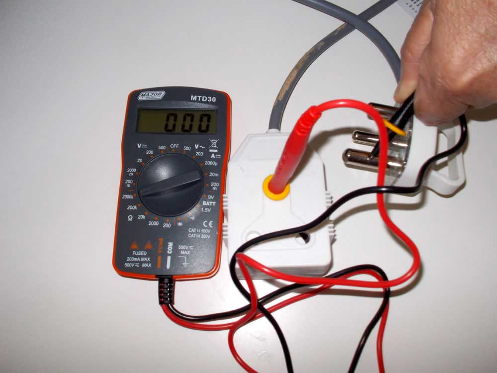
The resistance test works in a similar way as does the continuity test. The
device passes a small amount of electricity through the circuit and if there is
a connection, then it gives a readout of 000
or thereabouts. If there is no connection then a readout of 1 will result.
Here we have tested an extension cord. As you can see there is a circuit between the earth socket and the earth pin on the plug. Testing the other two pins and sockets confirmed the extension cord had been properly connected.
Resistance, as the terms suggests, is the material’s property to resist or stop the passage of electricity. The lower the resistance, the easier it is for the electricity to pass through the material. The higher it, is, the harder it is for electricity to pass. Hence, rubber has a high resistance, as does plastic, dry wood, dry masonry and so on; metals generally have low resistance and electricity will pass through them.
Caution:
It is as well to limit your testing around the home to this level. Once you start getting into checking wall plug sockets for example, any errors can be damaging and even dangerous. Rather leave that level of work to a qualified and licensed electrician.
Testing a
toaster
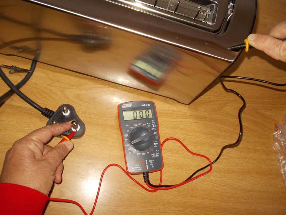
In this case we wanted to test a toaster to ensure that it is properly earthed,
or grounded, so that if a fault develops, it will trip the earth leakage safety
switch on the domestic distribution board.
With the selector set to measure resistance (Ω), we put one probe on the metal casing (where one is most likely to get a shock if there is a short, and the other on the earth pin on the plug. The readout is 000 – that indicates there is a path between the two and the appliance is properly earthed. We could have also tested using the continuity setting, in which case the readout would have also been 000 or thereabouts – indicating a complete circuit between the earth pin on the plug and the outer cover of the toaster.


Make up a
couple of clip leads
You will find a couple of clip leads – one red the other white, or black – a
very useful set of helpers when you need an extra hand. Each comprises a crocodile
clip on each end of a length of wire.
Ideally, you should use different colour wires, a red one and a black one are the best, as they will match the cords that come with the multimeter.
Each one is clipped between its probe (red to red, black [or white] to black) and can free up your fingers to change selections on the device. Once having made them up, check that each one completes the circuit… that there is a proper connection from clip to wire to clip.
Disclaimer/Advisory:
- Please note: any work associated with electricity or electrically-powered devices can be inherently hazardous and you should ensure that you exercise all due care when operating any such device, such as testing equipment such as a multimeter (also knows as a volt-ohm meter).
- Ensure that you read and understand the manufacturer’s operator’s instructions and guidelines completely. In the event that you are in any doubt whatsoever as to the meaning of any aspect of the instructions/guidelines,or the safe use of the device, obtain expert assistance from the manufacturer and/or a qualified and licensed electrician.
- All electrical testing devices are operated at the owner/operator’s own risk.
- Note that in terms of regulations, only a qualified and licensed electrician may work on the fixed wiring/electrical circuit of a home or business.