03 September 2024

Fold-out for a fry-up
It looks quite complicated but in principle this grid’s construction and design is actually quite simple.
When closed it is just on 50mm deep, 345mm wide (the frame is 310mm wide, and the dome nuts on each side take 20mm and an extra 10mm on the hinges), and 285mm in length.
When folded out, it is 548mm long, by 345mm wide and stands 175mm high with the feet extended. The actual braai/frying/cooking grid surface within the frame is 542 x 306mm – an ample area for quite a few steaks, chops, wors, frying pan, pot or kettle.
The only caution I would suggest is that though the hinges are very sturdy, rather not put them under undue strain, so place your heavier pots, kettle or whatever towards the ends and closer to the feet, rather than the hinge area.
Other than that, it’s time to fry solo – or as a squadron…. Geddit?
In passing, I used stainless steel through for this grid, but you could use mild steel as a cheaper alternative, but if you do, bear in mind it will rust and corrode over time.
Materials:*
- Stainless steel flat bar – 3x25mm – two lengths of 850mm bent** to a flat ‘U’ shape with 90° corners, with two arms of 270mm and a cross of 305-310mm.
- 6mmØ round bar – two lengths of 850mm, bent to a flat ‘U’, with a base of 290mm and two arms of 180mm, with corners a fraction more than 90° so that the arms diverge slightly from each other and are not parallel, and with the end of each bent outwards at 90°
- Four stainless steel hurricane fasteners – 33x33x170mm cut to make eight hinge pieces, each 2x55x30mm
- 26 lengths of 5mmØ threaded rod, each cut to a length of approximately 325mm, all cut from 1m lengths of threaded rod
- 52 5mm dome nuts
- 20 5mm flat washers
- Four 5x20mm flat washers
- Two 5mm wing nuts
- Two 20mm 5mm bolts
*Your local Mica will very likely stock the above-mentioned items, apart from the stainless steel flat bar and stainless steel round bar, but should be able to advise you as to a source. Please take note that you might have to search for a company that will cut your bars and rods to length as well… some sell these products in lengths of 6m only.
**The round bar is easy to bend to shape for the feet, but the flat bar is another issue. It can be bent using a club hammer and quite a bit of hammering, but for a couple of hundred rands or so, you could take it to a steelworks who could bend the metal bar very accurately by putting in what is called a brake. But if you go this route, ensure that you provide extremely accurate and CLEAR, CORRECT instructions to the company; once it is bent, you are stuck with it. Ensure that you also specify that both lengths must have precisely identical dimensions.

This illustration shows the positioning of the hinge fulcrum in relation to the bottom corner of the frame. Please note: rebate the corner of the frame ONLY once you have correctly positioned each hinge leaf and drilled the holes to attach them to the frame. The lower right detail shows how, with the hinge fulcrum centred on the corner, the grid closes up perfectly flat. If, however, the fulcrum is positioned below the arms, then the grid when closed forms an ‘A’ shape, slightly exaggerated in the far right lower detail for extra clarity. There is no issue with either option, but I preferred to have the frame lie absolutely flat when closed, as it reduces the space required when storing it.
Method:
- Stainless steel components are relatively expensive, but they last a lifetime.
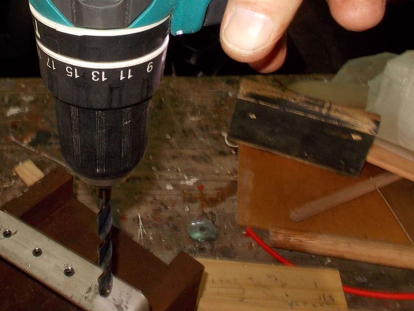
- As you will be cutting the ends of the flat bar and they must be very accurately cut at a precise 90° angle, it is best to either have it cut by at a metal-working company, or mounted in a cutting stand, as shown here. Just make sure you set the angle grinder in the stand very accurately.
- Check that the grinder is aligned perfectly vertically.
- Also check to confirm that it is at a perfect 90° to your workpieces when you cut them.
- My bench/engineers vice swivels through a full 360° so I could clamp the bar in the jaws, as shown, so that their surfaces engaged with the bar along its full length and I could then hammer the bar at the bending point and it would be true and 90°.


- Now for the hinges… I cut the eight leaves from four stainless steel hurricane fasteners. Note the use of the wood stop from an offcut to ensure each leaf was exactly the same length.
- This shows one of the hurricane fasteners before cutting, and one afterwards, with the resulting pair of hinge leaves.
- With all eight cut, I temporarily bolted them together.
- I clamped them in the vice and filed off any sharp cut edges, and also rounded off the cut corner, as much for safety as for its aesthetic effect.
- The sharp cut corners are now no longer sharp, or a danger.


- There are all the eight hinge leaves ready for fitting.
- I positioned one on the end of the frame arm and clamped it in position with the with what would be the hinge fulcrum centred on the bottom corner of the cut end of the frame arm
- This shows clearly how it is positioned, with the inset showing the enlarged corner centred on the fulcrum. I used the centre punch, with some masking tape wound around it to accurately centre the punch’s point dead centre when the two hinge leaf attachment holed would have to be drilled… do this ONLY when completely satisfied with the hinge leaf positions.
- I repeated the process on the other half of the frame and checked that the frame would close fully, and also open and lock flat. This takes a little unclamping, repositioning and reclamping before the correct result is achieved.
- I also checked, with the frame halves fully closed, that they met up properly, as shown here. At that stage I could use the sanding disk fitted to the angle grinder rebate the lower corner of the frame arm at an angle of 45° to accommodate the hinge fulcrum and drill the holes for the hinge fasteners.


- I lightly bolted the hinge pieces on to the frame ends to double-check that I had got the result I wanted. I had! This is the top view showing flat washers being used as spacers to allow the hinge leaves to overlap.
- This is the side view. Note that I did all this before drilling the holes for the grid bars. Serendipitously, the attachment holes drilled in the original hurricane fastener are exactly 20mm apart – my preferred grid bar spacing, so I used them as a guide to space the rest of the bars and also their position from the top of the bar.
- Initially I used strips of graph paper to mark off the 20mm intervals for the grid bars, but ended up using a marker pen to indicate the spacing.
- Then I made up this handy little aid…with the bar positioning marks lined up on the single panel pin and the two closer panel keeping the rod in position, I could very accurately drill the holes in the bar.
- Like this… (I have shown this with the graph paper strips in place, but as said above, using a marking pen is fine.


- You may get some swarf after drilling the holes and need to be removed as they are sharp and can give you painful scratches. (Swarf is the term given to the shavings of metal debris produced during machining.) You can remove it by lightly redrilling the hole edges with a larger bit than 5mmØ – I suggest an 8mm or 10mmØ bit. All you are doing is very lightly trimming the holes’ edges to skim off the swarf.
- Here is an example of how the holes ended up… perfectly aligned and perfectly spaced.
- This shows the difference between the hole (left) that has been cleaned of swarf, and one that has not (centre). At this stage I measured off and cut the 5mmØ grid bars. I cut one and checked it was the correct length, and then another 21. There are 26 in all. This is why I did not cut the last four… yet…
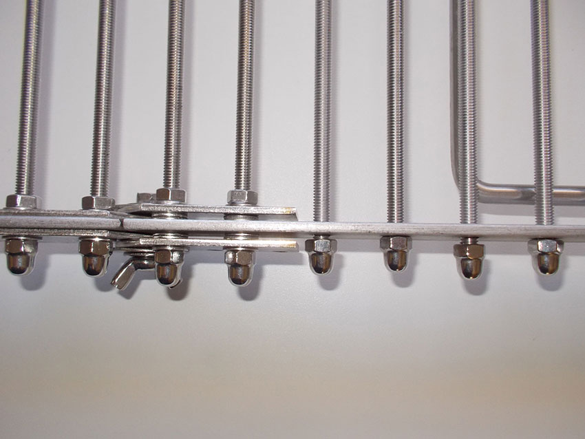
- This shows the side view of the hinge attachment.
- This top view shows very clearly how the four grid bars in middle double up as hinge attachment bolts. Also note that they have to be slightly longer as they must be long enough to pass right through the hinge leaves – including the outer one (that one on the right) that is spaced away from the outer edge of the frame so that its companion leaf can slide in under it between its inner surface and the outer surface of the frame.


- I used two fender washers, a 20mm bolt and wing nut as my hinge fulcrum on each side. Here is it half open.
- Here it is fully closed. Now you can see how the hinge leaves slide into position when the grid is closed.
- This shows the flat washer spacers, and also that only the dome nuts are used to secure the grid bars that are not fixing the hinge leaves in position. The grid bars doing the latter also have nuts on their inner ends, so that the hinge leaves are fastened very securely.
- Now let’s go back a step, and position the hinge holes for the feet… I positioned them 13mm in from the corner and 10mm down from the top edge. Then I removed the last grid bar, just for a moment, and very accurately drilled the 6mmØ holes for the feet ends.
- I wanted a height of about 170-180mm between the ground and the grid, so I cut two lengths of round bar of 850mm, used marks on some masking tape to mark the dead centre of each, and then a second mark on each side at 10mm in from the inner surface of the frame. You need to provide this clearance otherwise your feet will not fold in neatly within the frame.


- This shows the 10mm clearance more clearly.
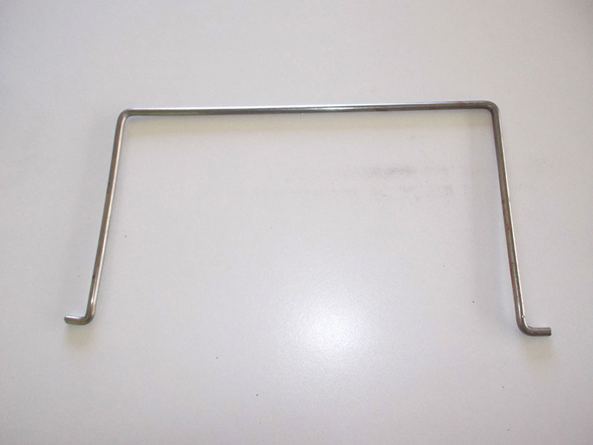
- Then I used the same method as I used with the flat bar to bend the feet to shape. Note that I have already made the bends in the ends where they will fit into the frame.
- There is one completed foot. Note three points: 1. It needs to lie absolutely flat on a flat surface, so both arms are properly aligned. 2. The arms need to be canted outwards a little, by 2-3°, so that their ends lock into their holes in the frame and will not slip out. 3. The second foot you make needs to be as close as you can possibly make it to the first – but check the first one first, to check that it fits as you want it to.
- Here it is, fitted to one half of the frame.
- Notice here that I have also cranked the end down a little so that it will allow the foot to lie as flat as possible on the lower edge of the grid when the grid is closed.


- Here it is fully extended. It rests at an angle of about 100°, so it is canted outwards and will support the grid over the fire.
- The lengths I chose give a height of about 170mm from the ground to the grid. Naturally, if you want to make your grid higher, or lower, you would simply adapt the measurements as required. Alternatively, and far simpler, either build a slightly deeper bed of coals, or pop the grid feet on a four bricks or whatever.
- Cleaning it after use is a doddle… folded up the grid fits very comfortably into a standard dishwasher.
- Here it is ready for use…
- And hot to braai… with an area of just under 550mm long, by 350mm wide, you have ample room for delicious goodies… it’s time to meat the nation! Pardon the pun.


Next month we are going to show you how to make a handy bag for this grid.
Panel:
These materials, with the possible exception of the stainless steel 3x25mm flat bar and the 6mmØ round bar, are available at Selected Mica Stores. To find your closest Mica and whether or not they stock the items required, please go to www.mica.co.za, find your store and call them. If your local Mica does not stock exactly what you need they will be able to order it for you or suggest an alternative product or a reputable source.
Project guide
TIME: 6-8 days
COST: R1000+ for rust-proof stainless steel, but less using soon-to-rust mild steel
Skill: 4
Assistant: No
Tools required:
Drill, preferably mains, but you could also use an 18V cordless drill driver, club hammer, large bench (engineers) vice, angle grinder (preferably mounted in a cutting stand), cutting disks and sanding disks, socket set. Ideally, if you have a drill press, drilling the holes for the grid bars, hinges and feet in the flat bar will be made a lot easier.