04 June 2024

Make the move – enhance your security with a motion-sensor light
It wasn’t that long ago when one had to fit a motion sensor, such as a passive infrared sensor (PIR sensor) into a circuit in order to trigger a light or alarm when infrared (IR) light radiating from moving objects in its field of view triggered the unit.
Nowadays, though there is still very much a place for PIR sensors in all sorts of applications (these sensors are very often used in security alarms and automatic lighting applications) it can be so much simpler to set up a motion sensor alarm, because there are light bulbs – in both versions… the screw-in fitting and also the bayonet fitting, that are simply inserted into a standard light bulb socket, turning it into an automatic motion-detecting On/Off sensor.
Please note:
Please note, however, that some of these bulbs take a while – anything from an hour to even a few hours to “acclimatise” or “set” their sensor to its situation. So when you switch on, the bulb will often go on and then stay on as its sensor works through the process.
The hassle is that the packaging does not always point this out, so you can be forgiven for thinking the bulb is faulty.
But give it time to settle in, and then if it still stays on, take it back to the shop for a replacement.
Some models have a sensor arc of 230° or so and when triggered will stay on for about 3 minutes. They will then automatically switch off – unless triggered anew by another IR source on the move.
Output can be in the range of about 810 lumens or so, with a power consumption of around 9W, which ensures added security at minimal cost. They are also designed for long life – in the region of 15000 hours, depending on the brand and model.
Also please note, however, that these bulbs are not Day/Night sensor types; they go on only when triggered by motion within their field. Day/Night bulbs switch on when the ambient light level falls to a particular level, and then they stay on overnight until the ambient light level increases again as dawn breaks, when they then switch off. Hence they will use more power during the dark hours, than would the motion sensor version, which switches on only when triggered.
Also please note, these bulbs are not dimmable and also that they can, possibly, be triggered by your moggie or pooch trotting past, or even a small bird on his or her way to a new insect feast.
And we’re off…
Materials:
- Mounting plate (if required) for the all-weather light fitting. I used a piece of treated off-cut SA pine for this purpose.
- Motion sensor light bulb
- Twin-core flex of the required length*
- All-weather housing – if mounted in an exterior position
- Plug
- Power source
- Hot glue (optional)
- In-line switch (optional – these bulbs are designed to remain switched on continuously, so once you switch them on, leave them on [not that you might be able to prevent them turning off if you are prey to Eskom blackouts. If that happens, note that the bulb will again very likely need to “reset” its sensor after each blackout])
- Attachment screws
*Note that if any part of the cord will be exposed to prolonged direct sunlight, you should fit one with correct specification – the assistant in your local Mica’s electrical department will be able to advise you on this.
Method:
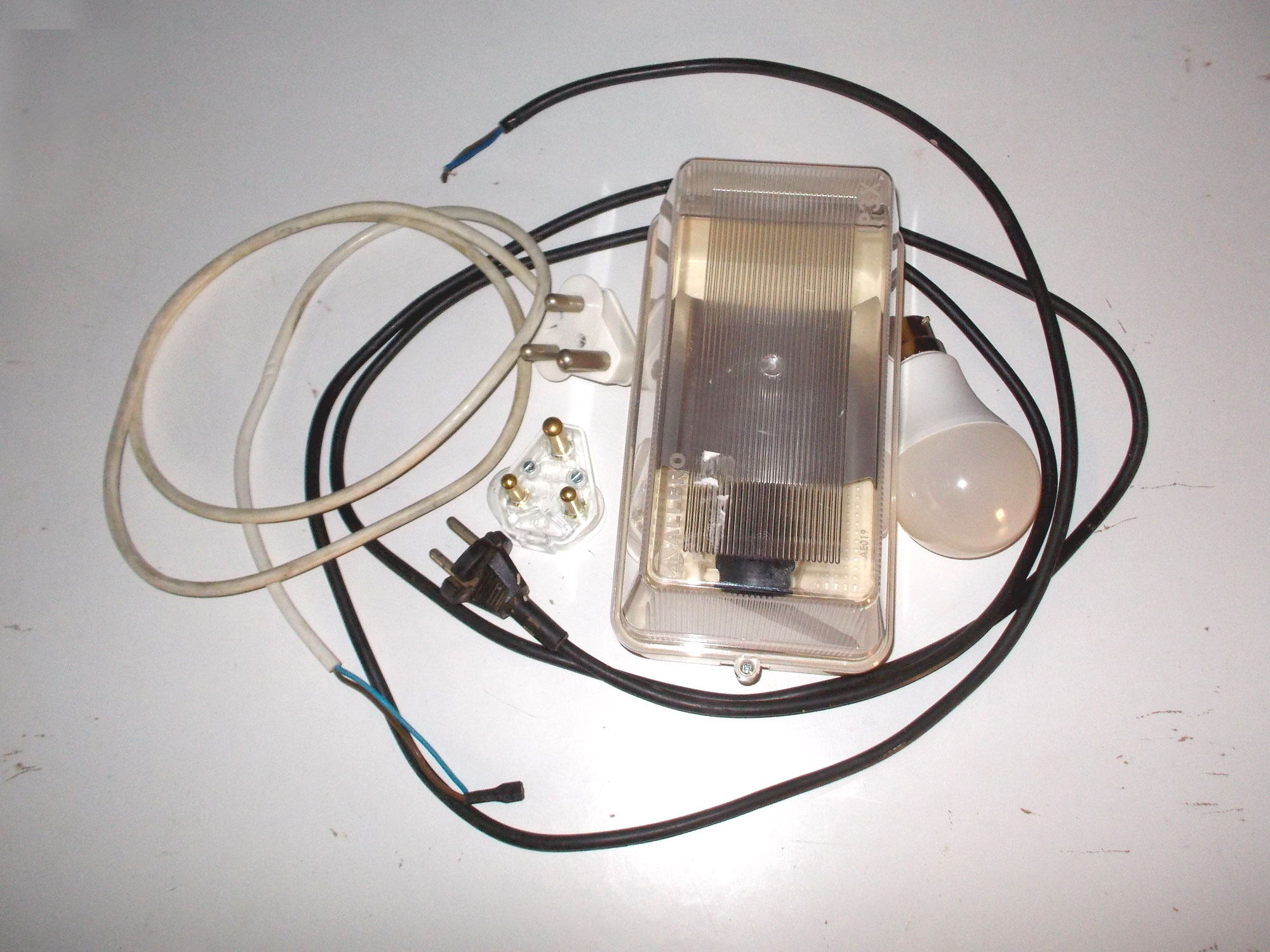
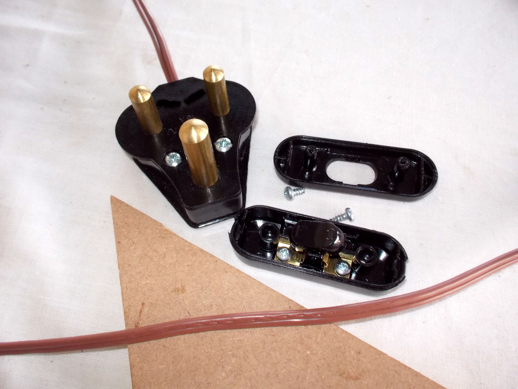
- Here are the basic components you will need. Hint: If you strip down old kitchen appliances, for example – for fasteners, screws, springs and so on – save the power cord as well. Sometimes they can be useful, such as in this case, though I didn’t use it this time.
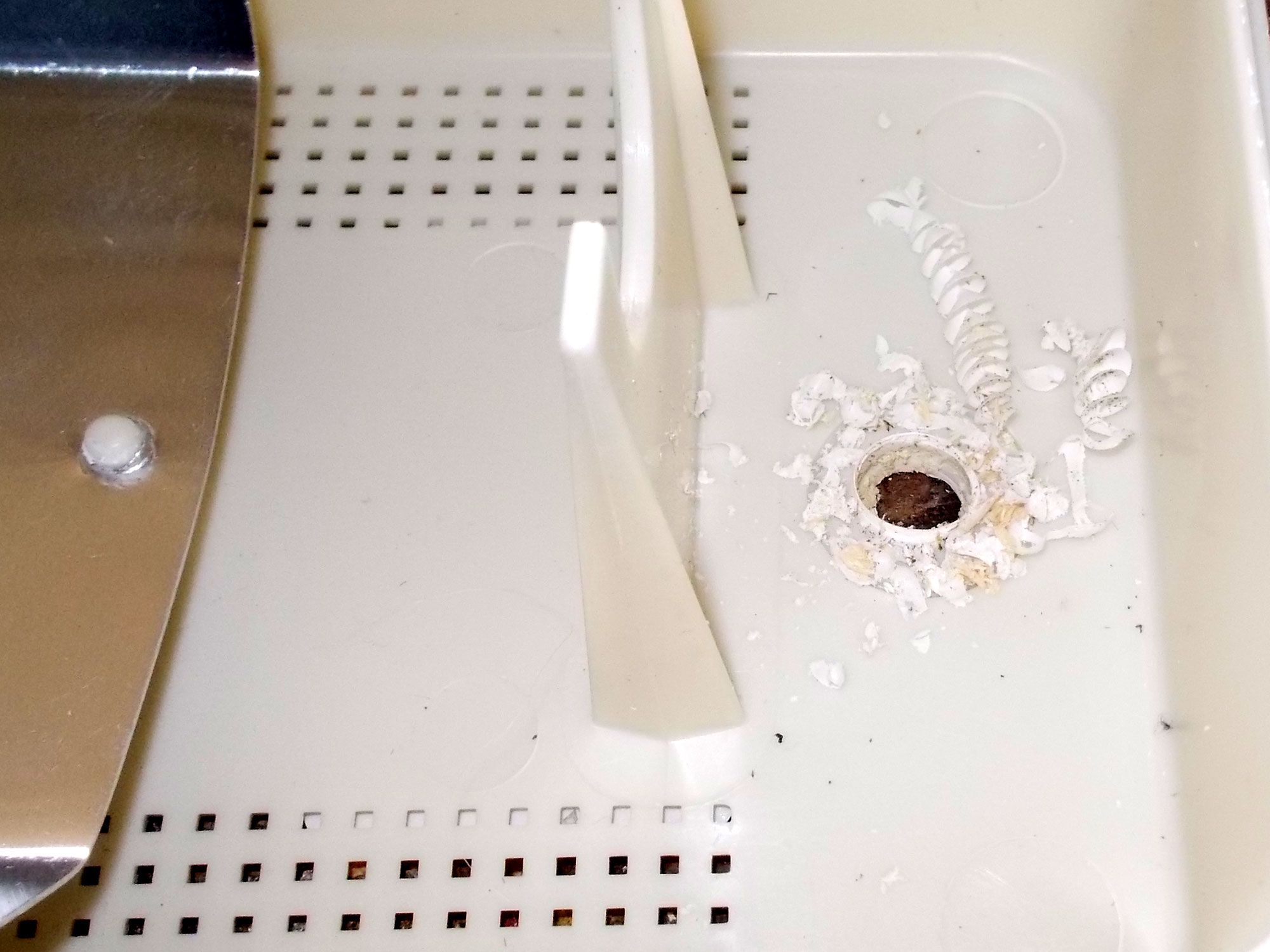
- First of all, remove the bulb fitting and drill a hole in the base of the light fitting housing for the power cord. Cut your base – in this case I used an off-cut of treated SA pine 22x69x240mm. This is long enough to accept the light fitting, which is 200x110mm. Place the fitting in position on the base and drill the hole through the base for the power cord in the corresponding position.
- Pass the power cord through the hole you drilled in the fitting and attach the bulb socket to the end of the cord.
- When connecting the 2 wires, strip the insulation back only enough to bare enough wire to make the connection.
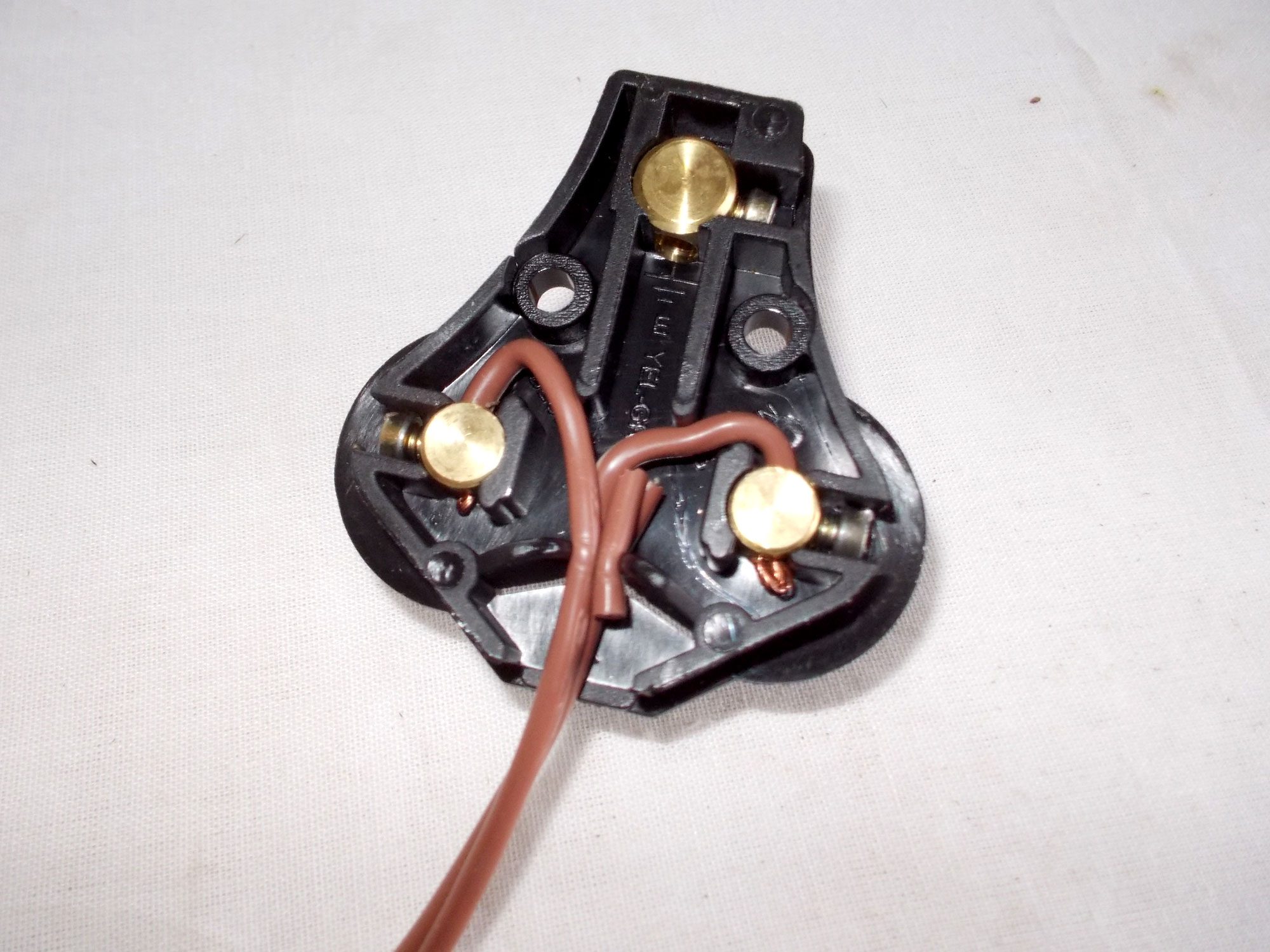
- Just for information, this shows how a 3-core cord is attached to a 3-pin plug. With the pins facing away from you, the b[R]own lead is attached to the [R]ight hand (Live) pin and the b[L]ue lead is attached to the [L]elf-hand (Neutral) pin. The Green/Yellow Earth or Grounding lead is attached to the top large pin with the Earth symbol – inset on the image – next to it.

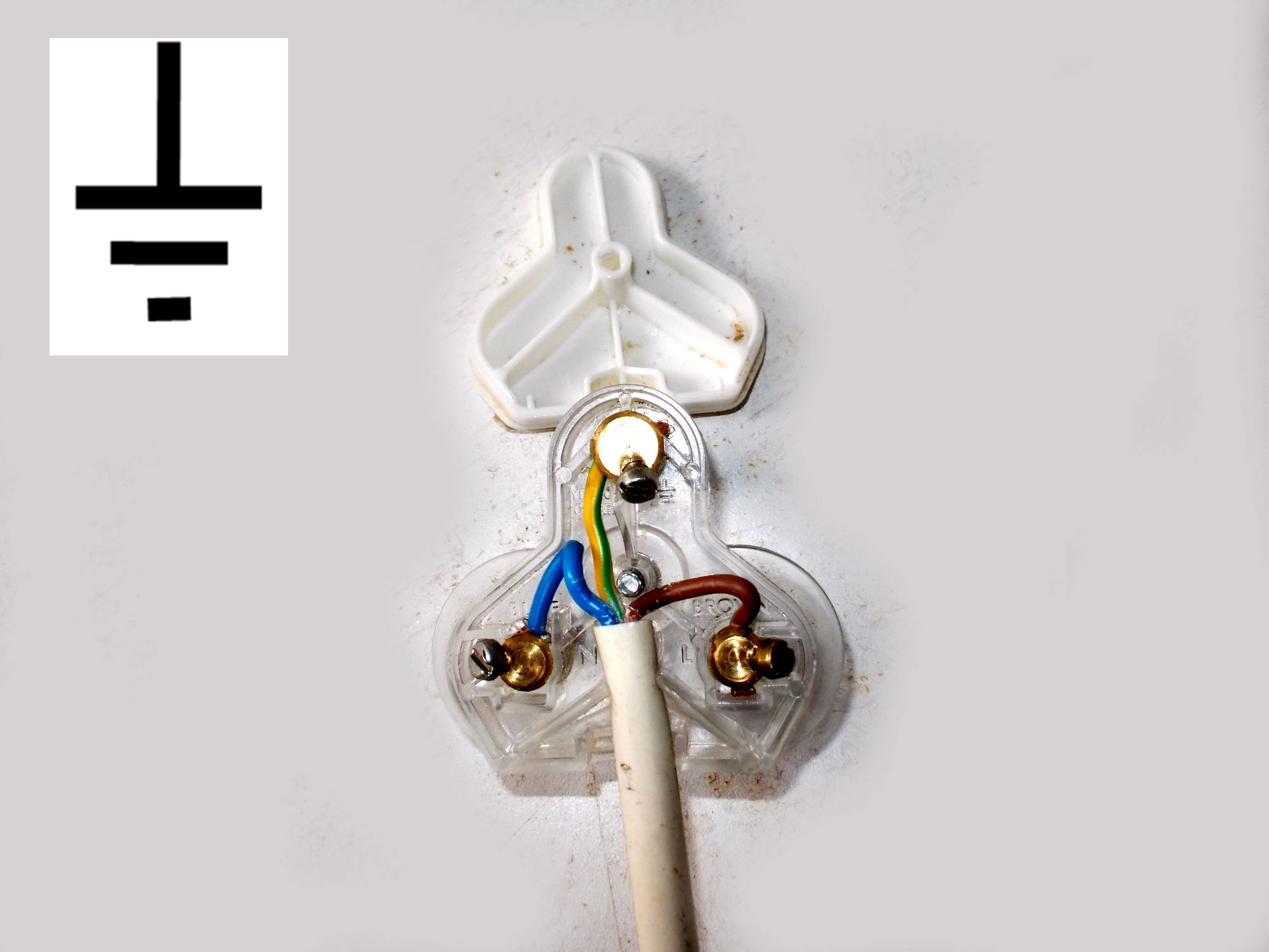
- The light we are fitting does not have an earth, so use either a 2-pin plug, or, as shown here, a 3-pin, with the twin flex leads attached to the Live and Neutral pins. There is no lead to be attached to the large Earth/Grounding pin.
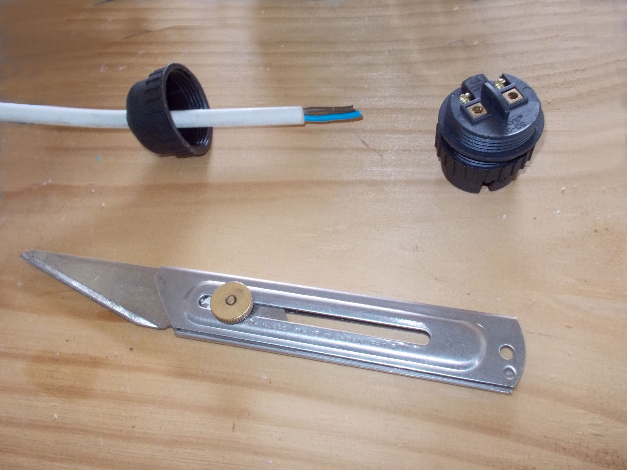
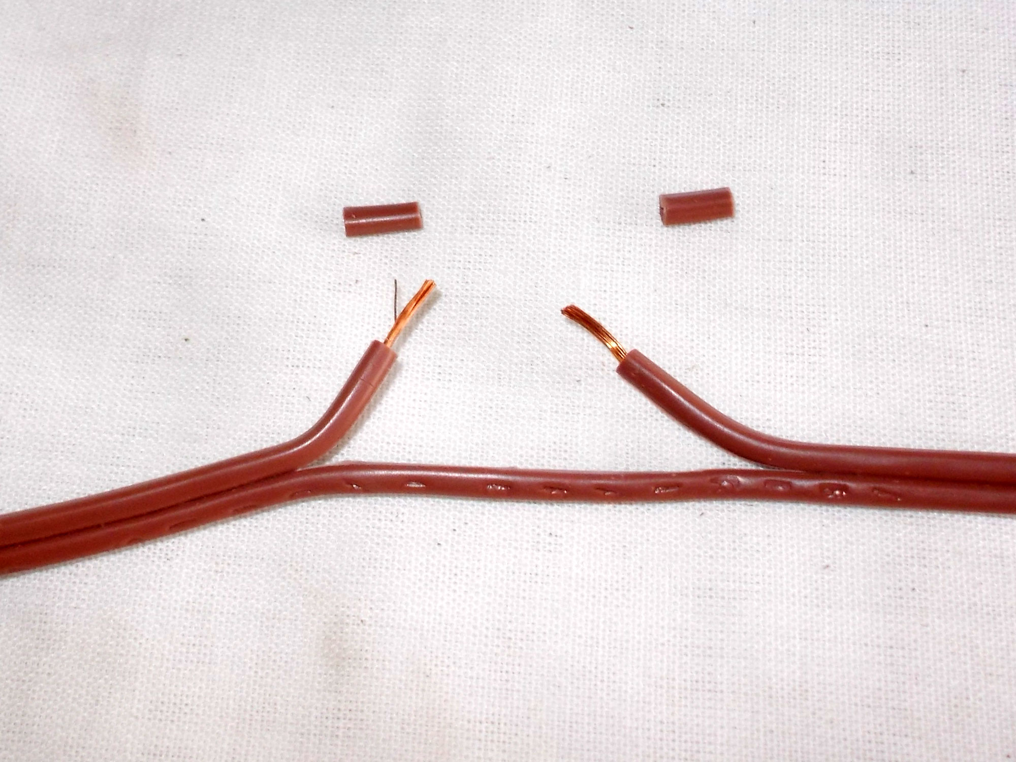
- As mentioned in the text, there is no real need for an in-line switch, but if you choose to add one, disassemble the switch.
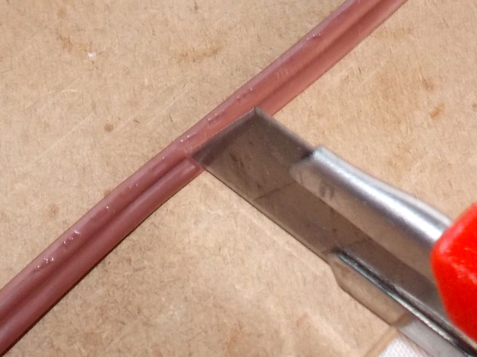
- With a sharp blade, carefully cut just one of the flex leads, as shown here – taking care to not cut into the insulation on the other lead.
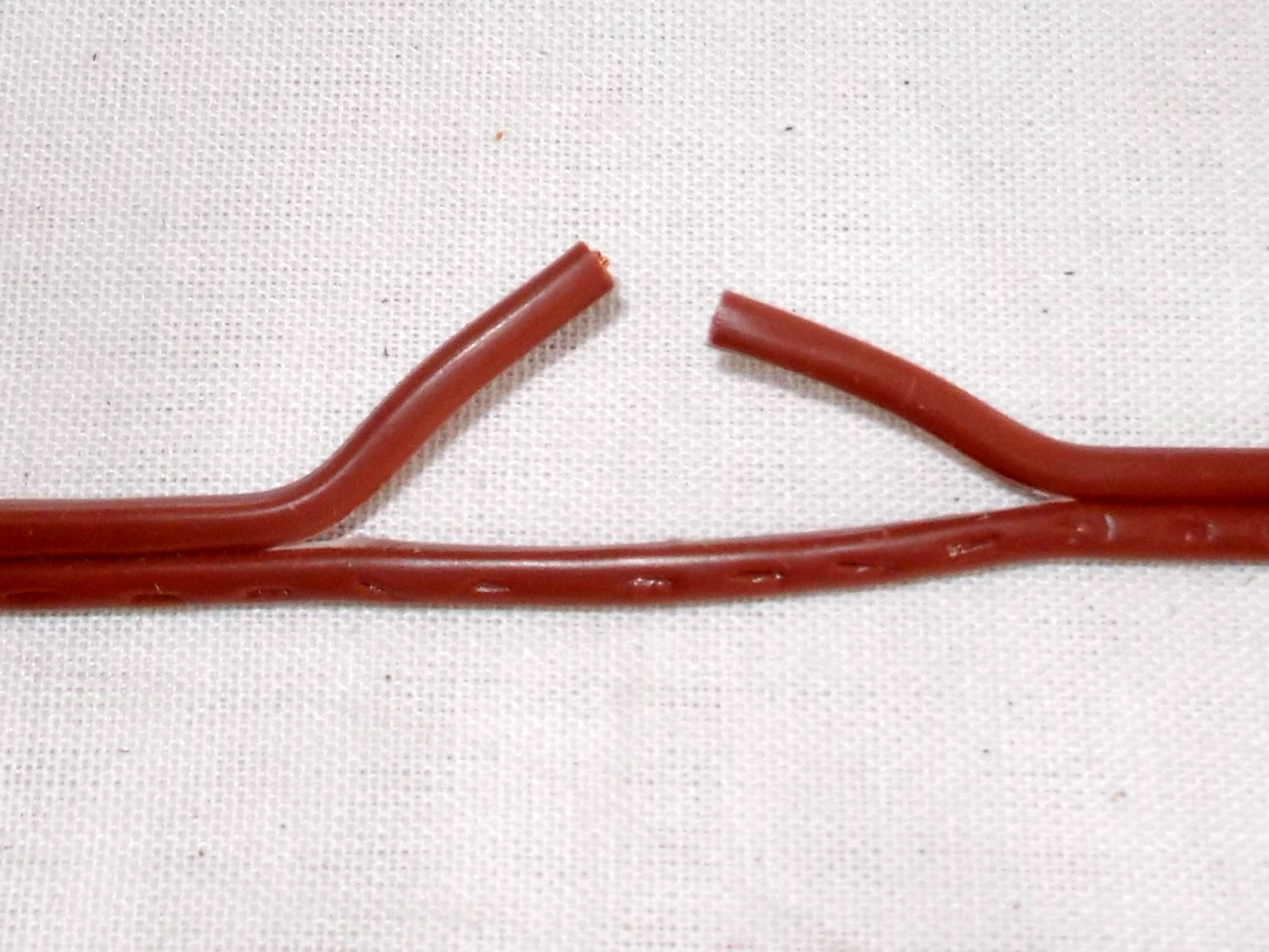
- Do not cut the 2 cut ends back – leave them the same length.
- Now strip off about 5-6mm of insulation on each and connect them to the plug’s terminals.
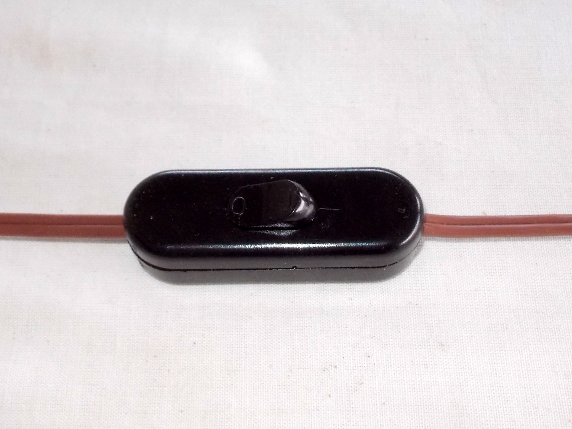
- The uncut flex lead passes along the side of the switch assembly, after which the 2 halves of the switch are reattached.
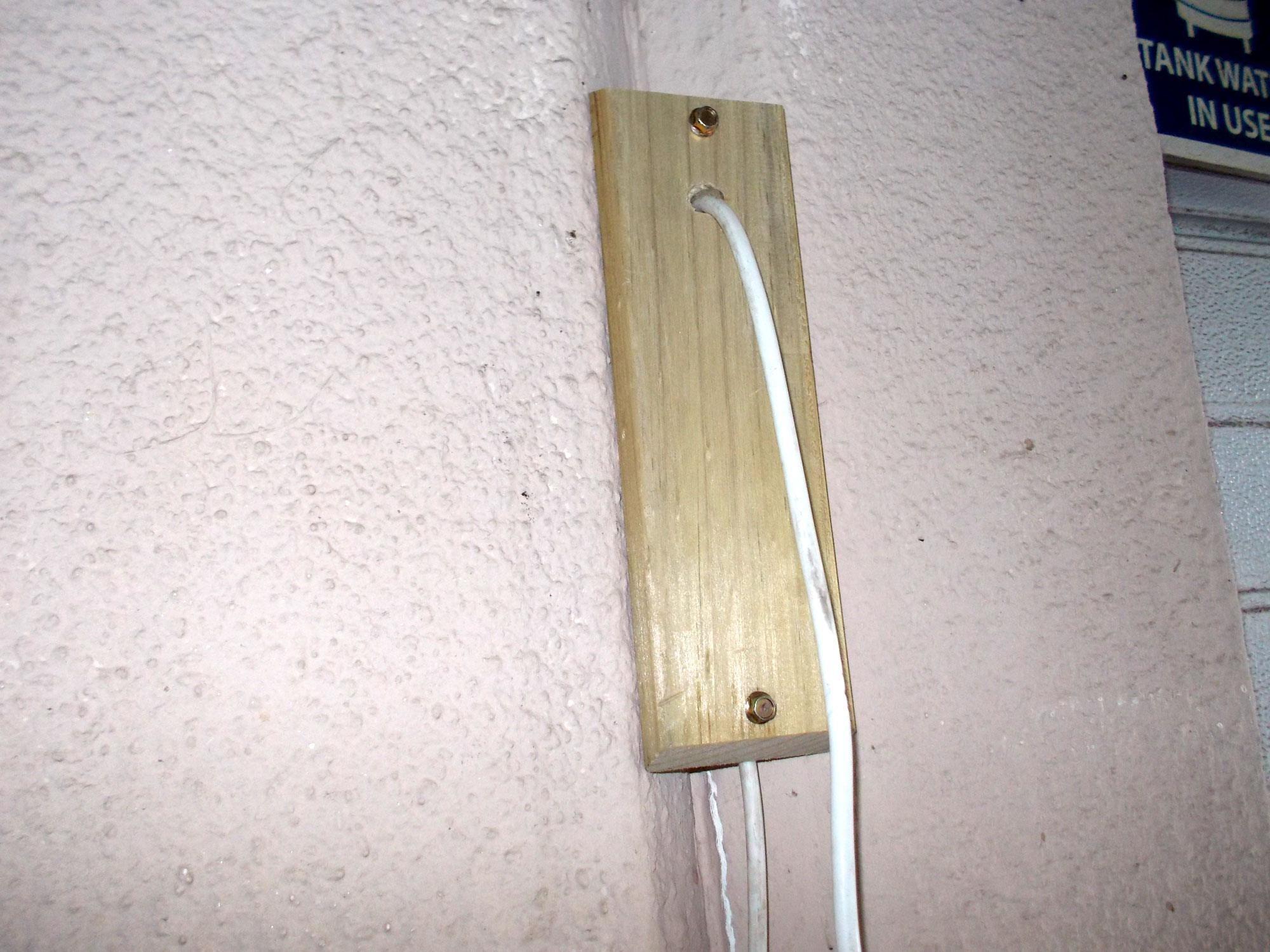
- Now you can attach the base to the wall. Ensure that the power cord is well clear of the attachment screws; it is essential that the cord’s outer insulation (and hence either of the leads’ insulation not be damaged in any way as it could cause a short circuit or even make one of the attachment fasteners “live” and hence, potentially lethal. Pass the cord through the hole drilled the base. Note that if you are attaching the fitting directly to the wall, then no base is required. So at this stage, you have the cord passing through the fitting and base and with the bulb fitting attached to one end and then the plug is fitted to the other end.
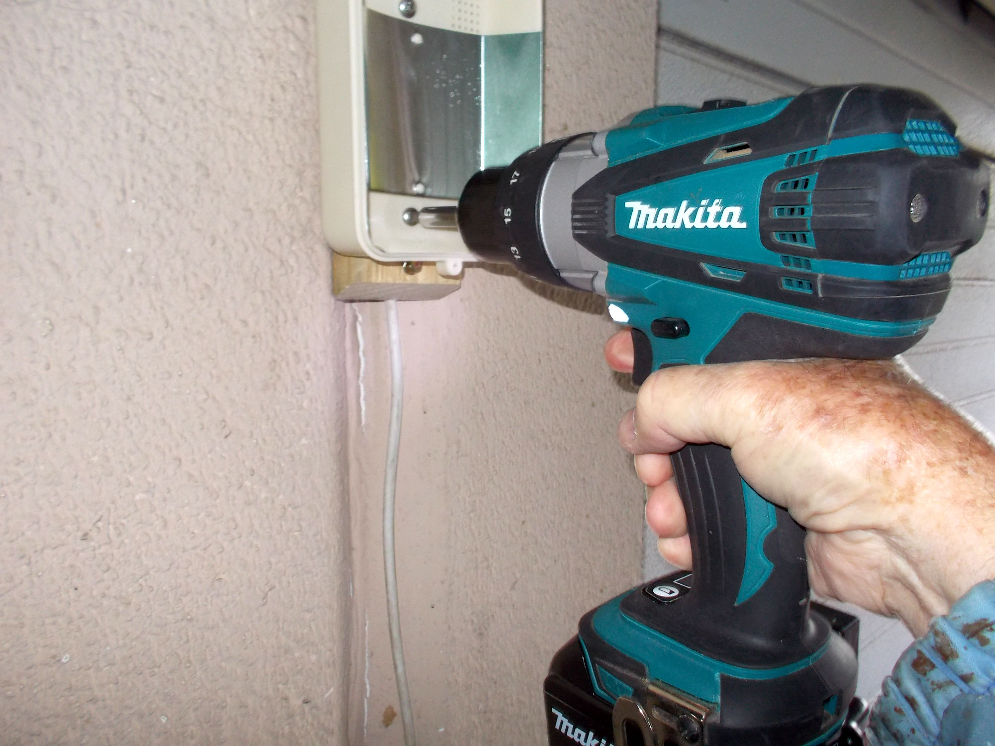
- I used pan-head screws – they have a flat underside to the head – to secure the light fitting to the wooden base. If you have to use screws with a CSK (countersunk head), then cushion each one with a washer because if you tighten the screws too much, you risk cracking the plastic base of the fitting.
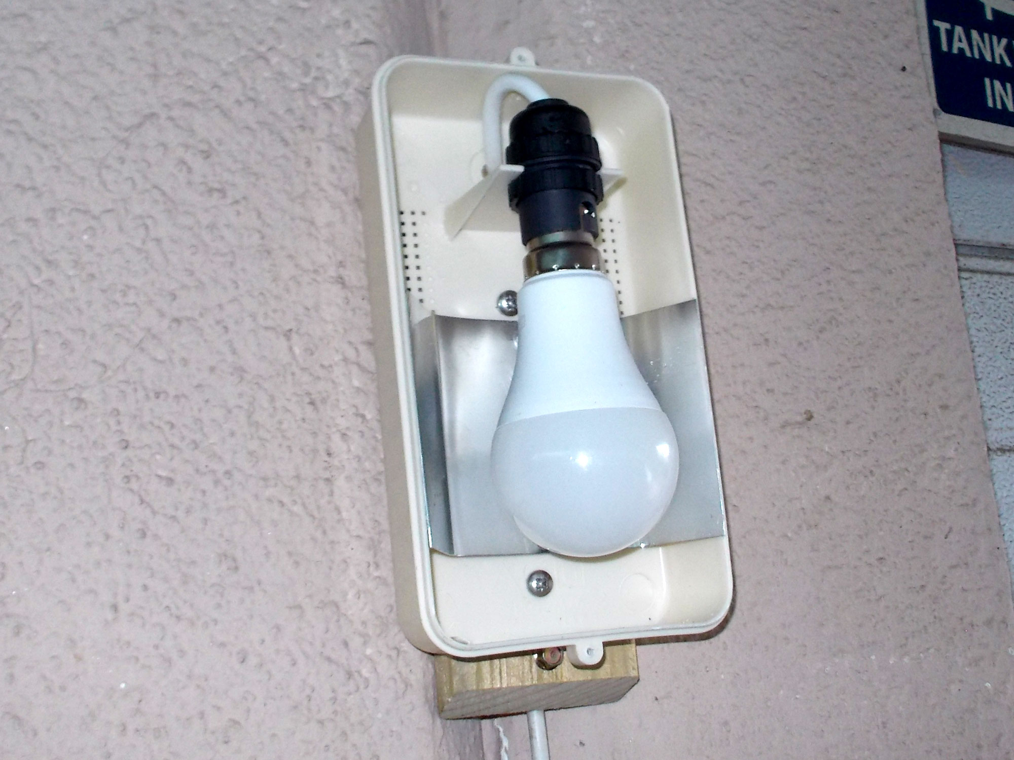
- Then I fitting the bulb socket into place, fitted the bulb, and reattached the front transparent cover to the light fitting. I also hot-glued the cord down the wall – on the junction of the 2 garages. Note that the cord connecting to the bulb fitting loops up from the hole in the base. This means any water that happens to pass down from above the fitting cannot use the cord to penetrate the housing as it would have to flow UP in order to reach the bulb fitting. And that doesn’t happen – unless it is pumped upwards.
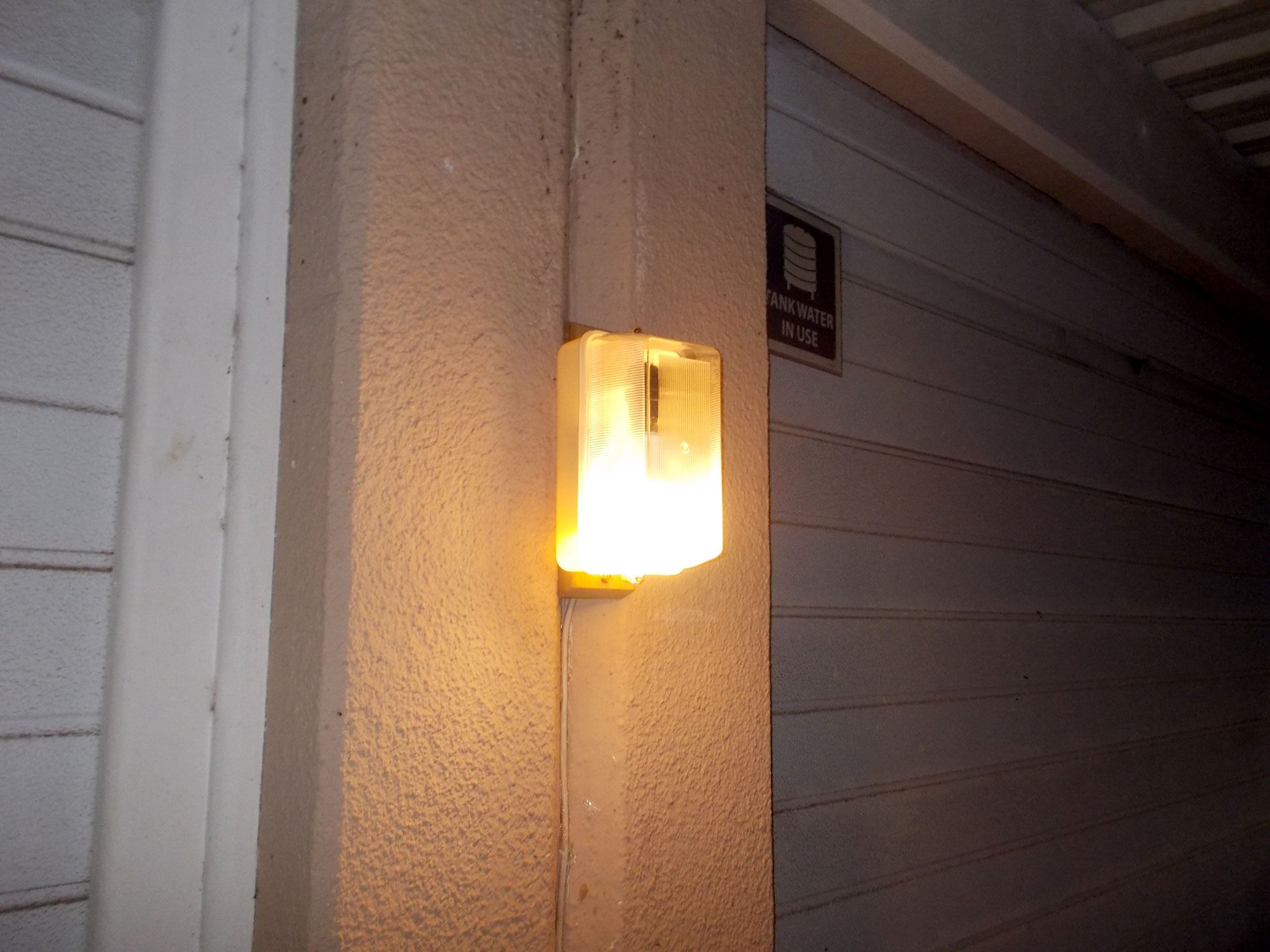
- I plugged in the cord to the power outlet and turned on. Later, I went out after dark and… let there be light! (For 3 minutes, anyway, until I moved again.) So it is now very much as case of “Go head… light my night. Are you feeling lucky, huh?”
Panel:
These materials are available at Selected Mica Stores. To find your closest Mica and whether or not they stock the items required, please go to www.mica.co.za, find your store and call them. If your local Mica does not stock exactly what you need they will be able to order it for you or suggest an alternative product or a reputable source.
Project guide
TIME: An hour at most
COST: R200
Skill: 1
Assistant: No
Tools required:
Jigsaw, drill/driver.