08 January 2024

A Cool Idea
You will have noticed that we live in a country prone to power outages, even though they may well decrease somewhat as election time draws near next year they may well increase again shortly thereafter, and probably be with us for some years. Hence many of us have invested in alternative sources of electricity – everything from back-up inverters, to rechargeable lamps, generators and so on.
I have had quite a large system installed, and it incorporates an 8kVa inverter.
This is mounted quite high on the wall, and generates heat when operation. Now, as we all know, warm air rises, and thus I decided to install a cooling flue that would allow that warm air to escape, to be replaced by cooler air.
I also decided that to ensure no rainwater could possibly drip on to the inverter or anywhere into the room that the cooling flue would not pass out through the roof.
I also used that well-known principle that when air is blown across the top of the tube or pipe, it creates a lower pressure in the tube or pipe and so air is drawn out. This would ensure a through-flow of air through the flue… warm air passing through and out.
Materials:
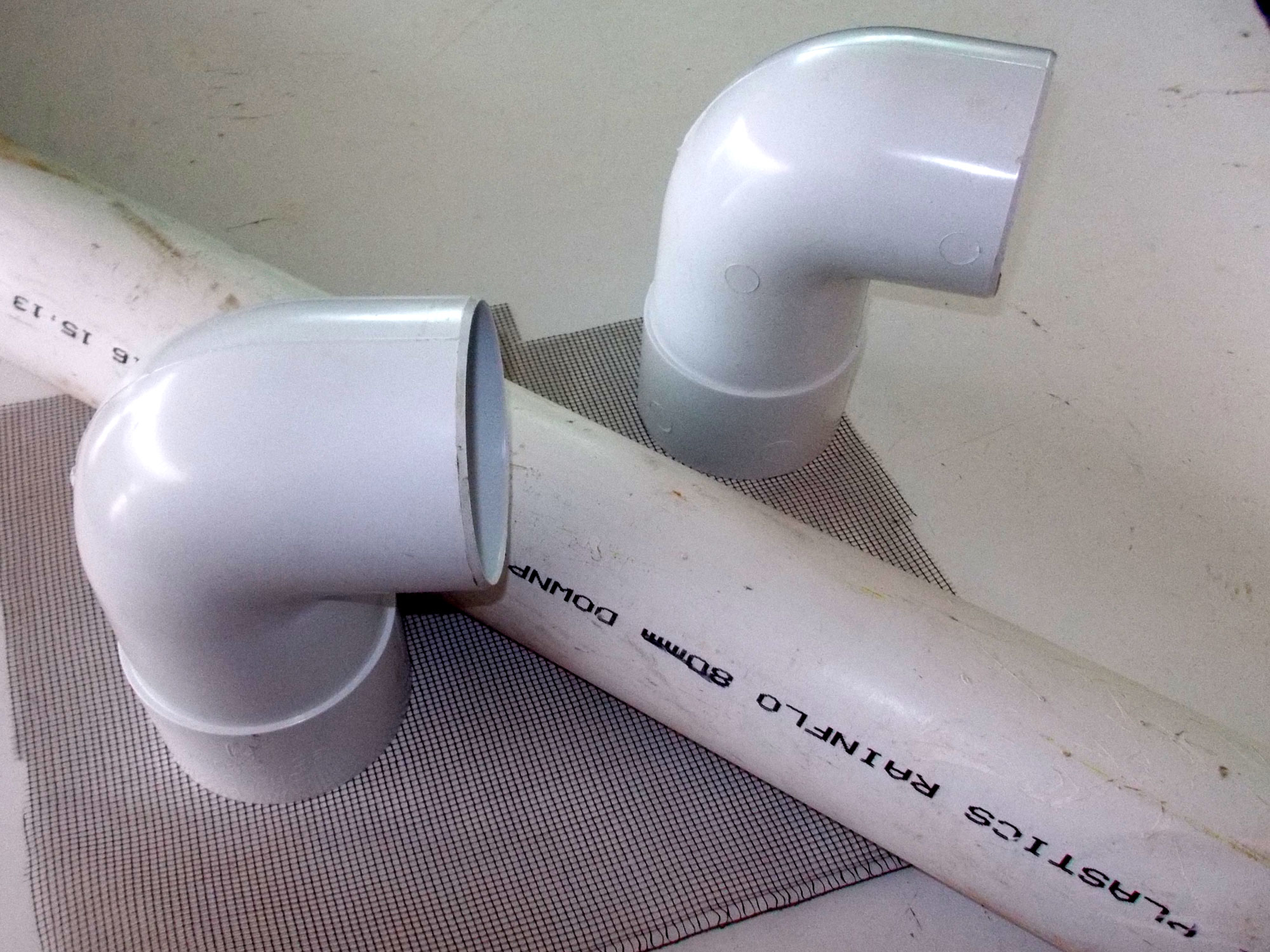
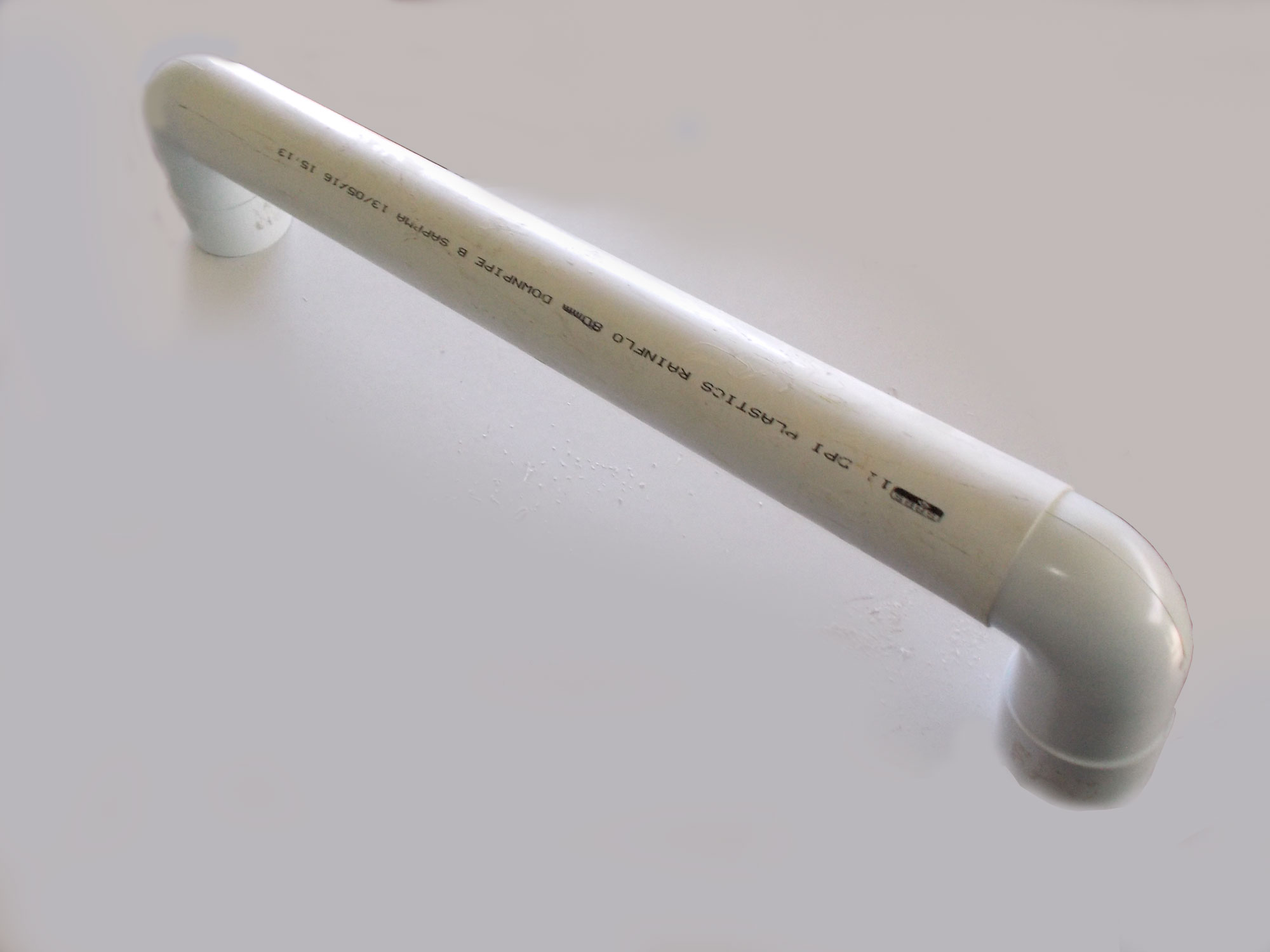
- PVC 80mmØ white drainpipe, length as required*
- Two 90° 80mmØ bends
- Two 80mmØ sockets
- Fine mesh – 300x300mm square
- Exterior filler
- White touch-up paint – or colour as required
*The length of pipe you will require will be determined by what is required in your particular circumstances.
Method:
- The two 90° bends and the pipe, all sitting on the piece of mesh. At this stage I had not yet decided that using socket joiners would be a far better idea than my first (see below) – but live and learn, eh?!
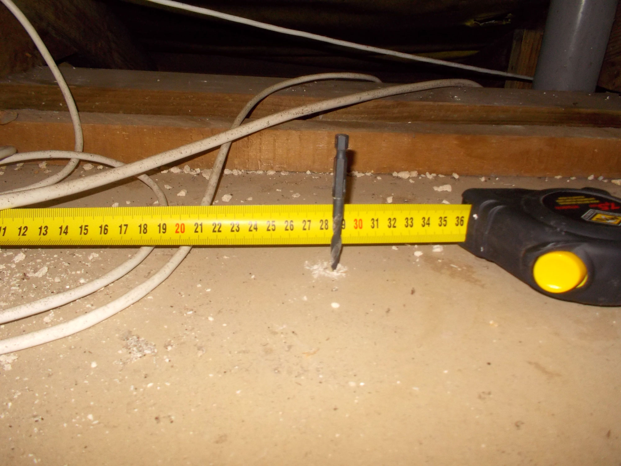
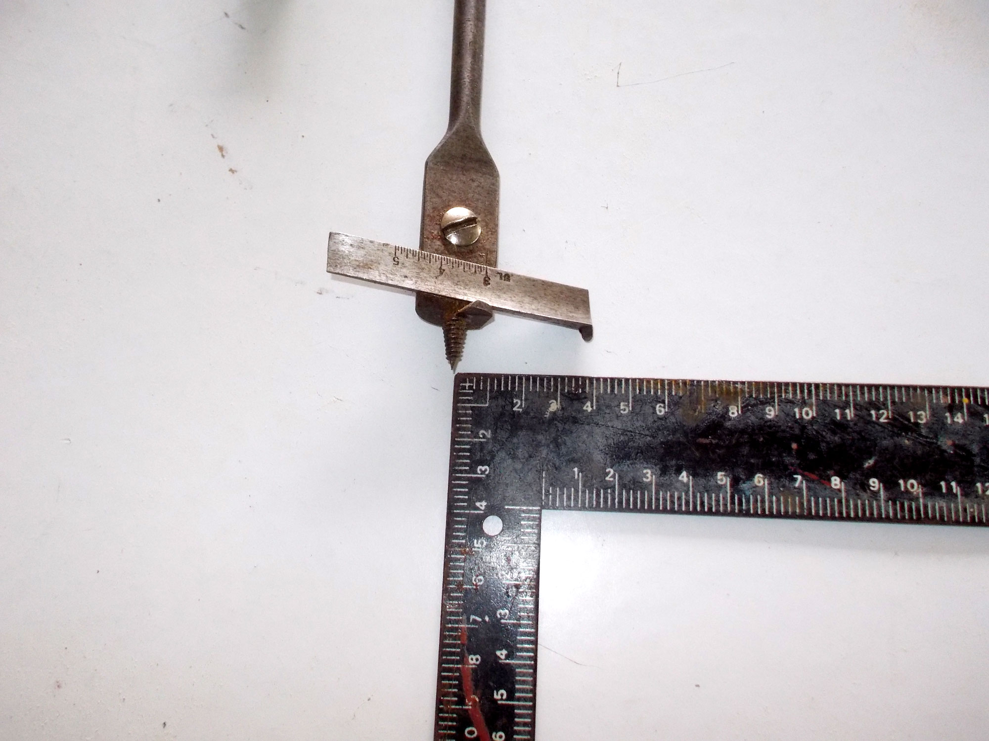
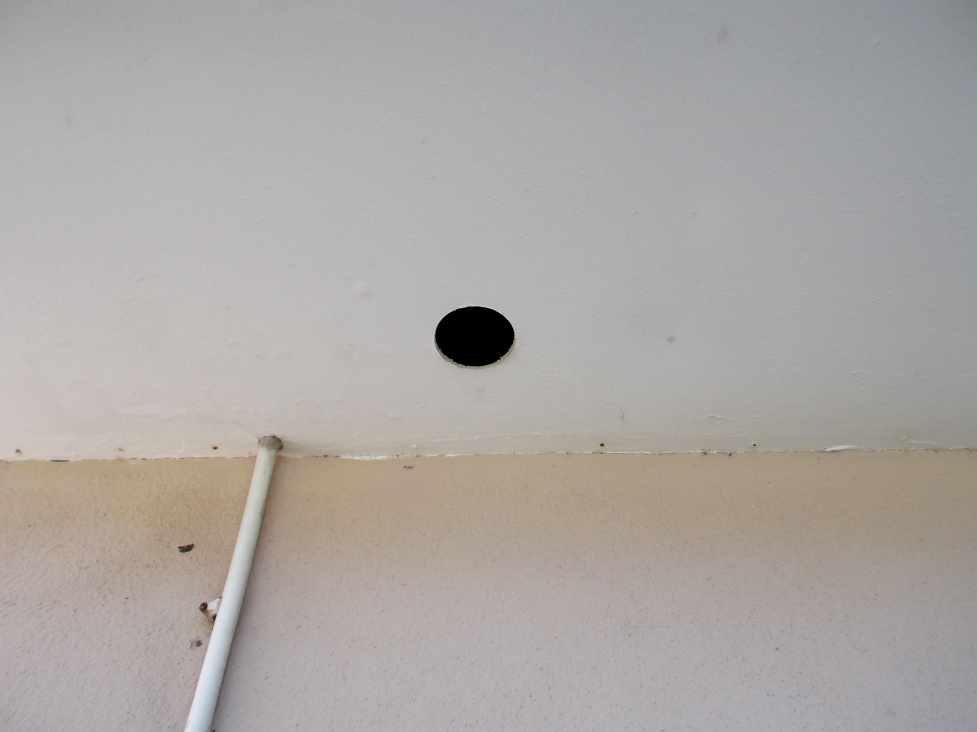
- I measured off the centre point of the inlet (interior side) of the flue. I worked from the ceiling space as the wires shown in this image are part of the security system and I did not want to damage any wiring.
- With a little adjustment or two, I drilled the pilot hole for the interior end of the flue.
- Then I lined up as closely as I could to 90° and drilled a second pilot hole in the ceiling board under the roof eave, which is where the longer outlet of the flue would be positioned.
- My first thought was to use an expansion bit, as shown here, to cut the 80mmØ holes for the piping, but…
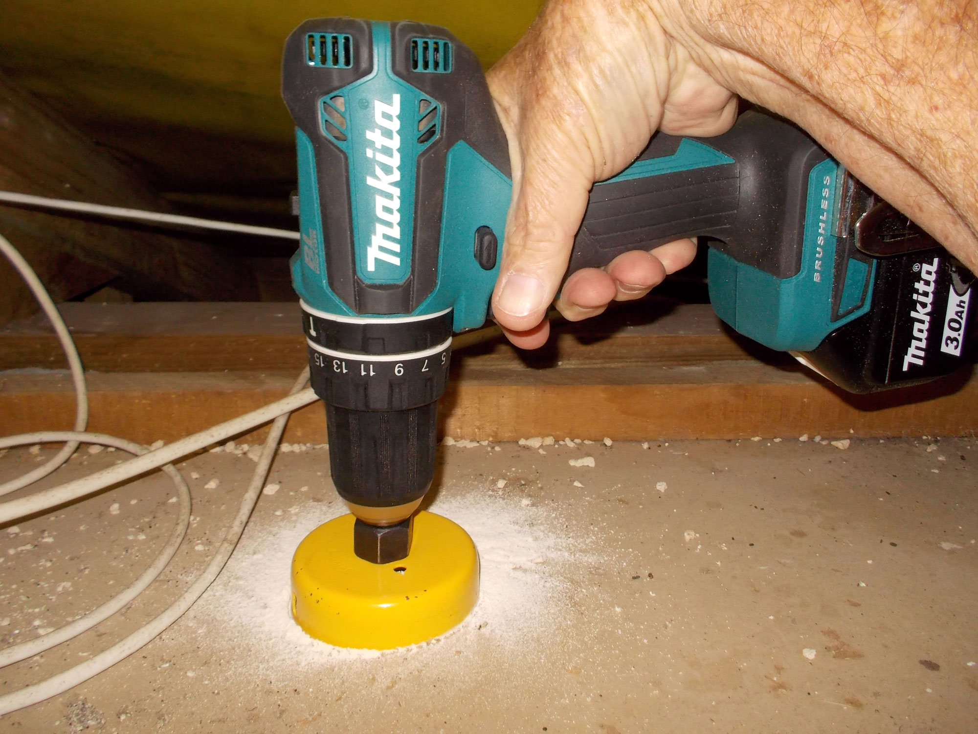
- Then I decided to rather use a holesaw, slightly smaller in diameter than that of the pipe, and then use a rasp to enlarge the hole as required. I made the change because I was a little concerned that the expansion bit might rip the ceiling board and cause large cracks or damage it whereas the holesaw, with its smaller teeth would cut a smoother-edged hole in the board with little if any risk of excessive chipping and fracturing of the ceiling board.
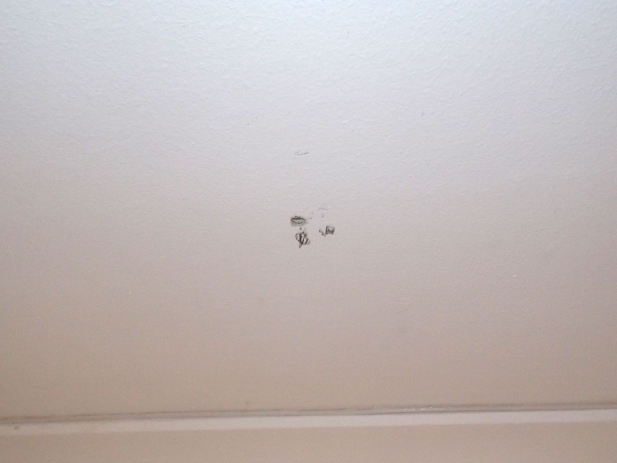
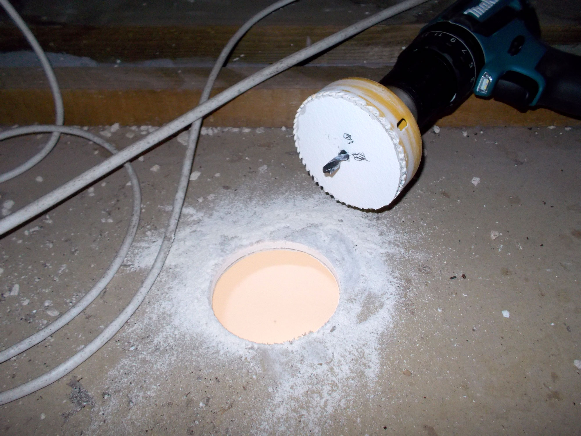
- So the holesaw it was and this is the result. Again, to ensure no damage to the security system wiring, I drilled from the ceiling space for the inlet (interior) end of the flue.
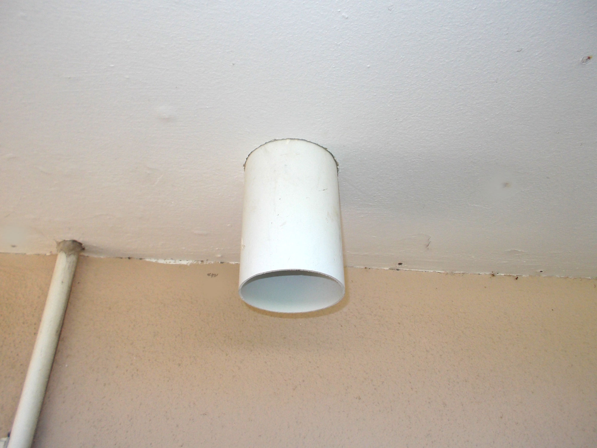
- And here it is, centred in the ceiling.
- I repeated the process for the outlet end of the flue, but in this case could work from the outside (no security system wiring or water pipes, for instance) to worry about.
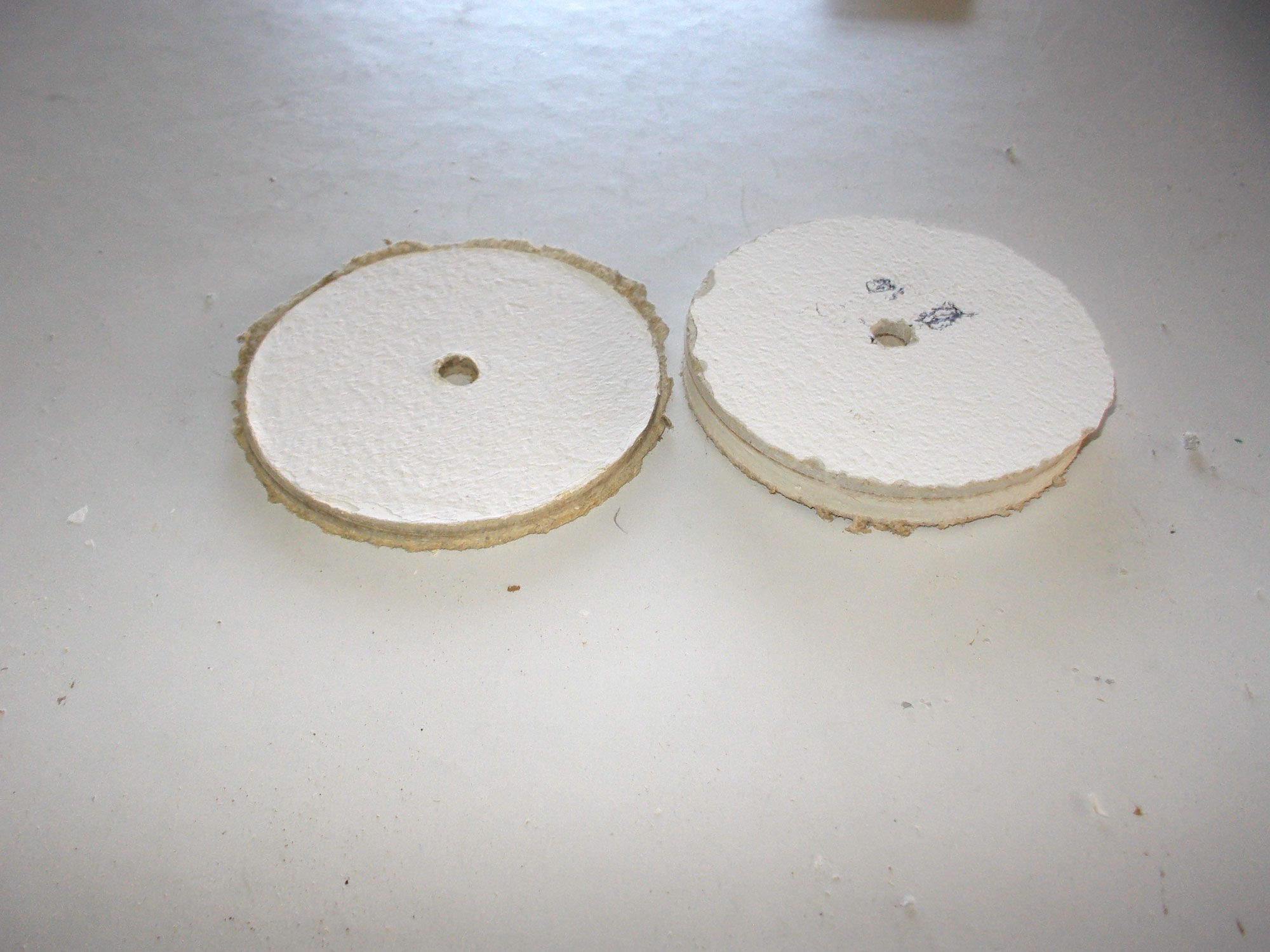
- Note the different thicknesses of the ceiling boards… the interior board (right) is 10mm thick, while the exterior board (left) under the roof eave is about 5mm thick.
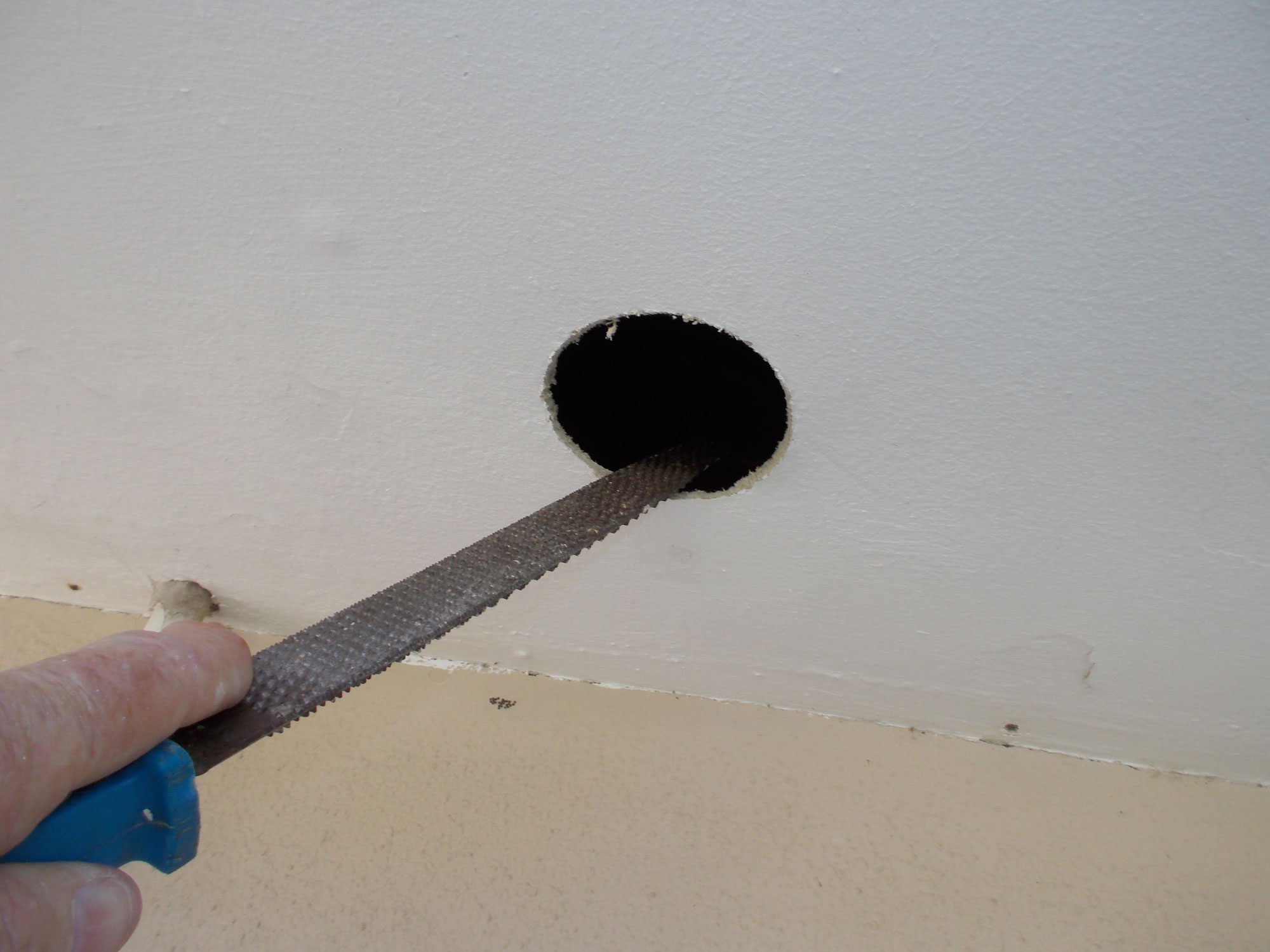
- I enlarged the holes using a rasp, but to ensure that the board chipped as little as possible on the visible surface, I applied only a little pressure and worked from the lower surface, up into the ceiling space area.
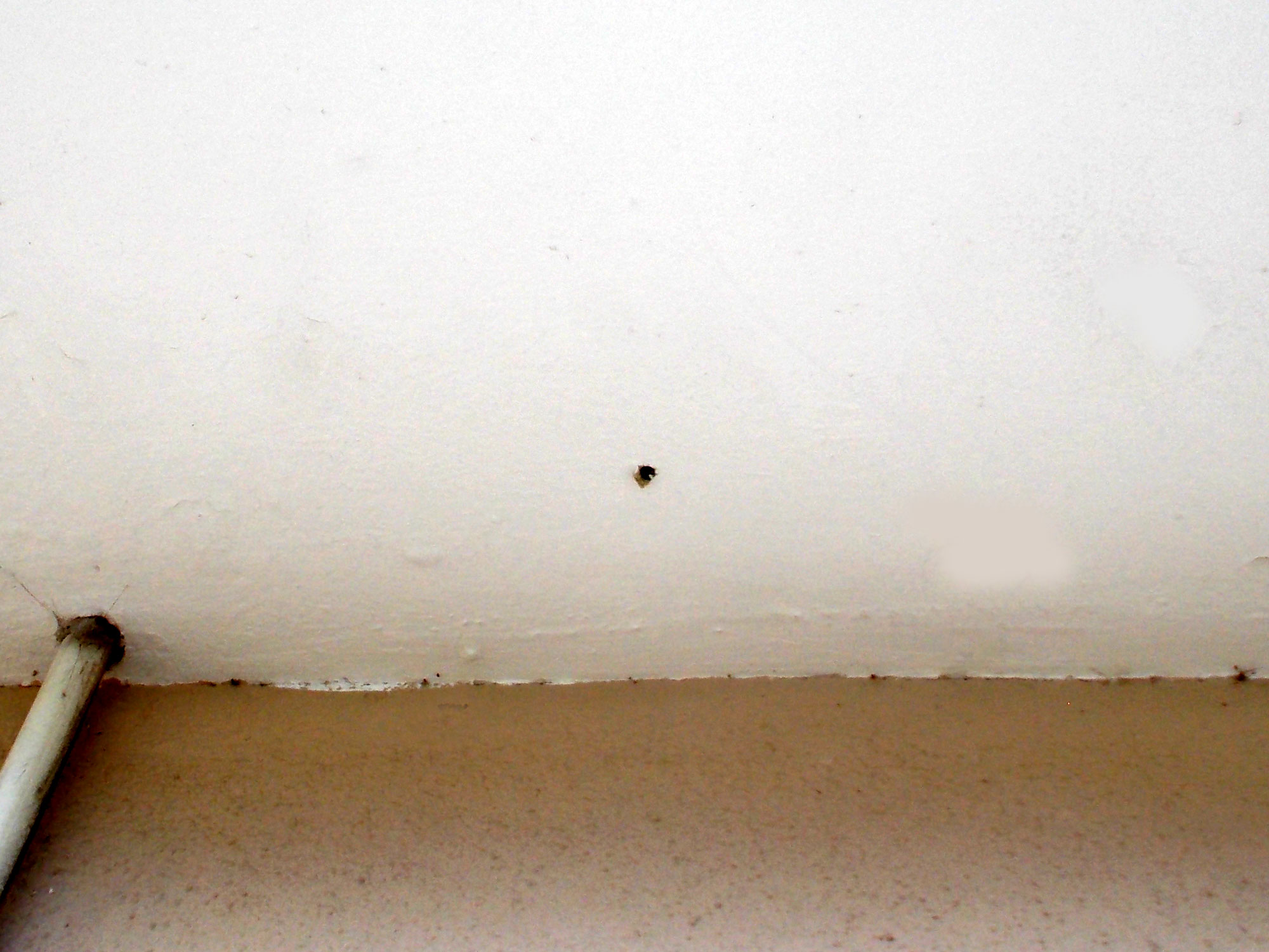
- I kept the hole just large enough for the flue pipe, and as you can see, even with a lot of care, there was a little chipping away of the board. But that would be covered later with filler so no problem. This is the interior inlet end of the flue.
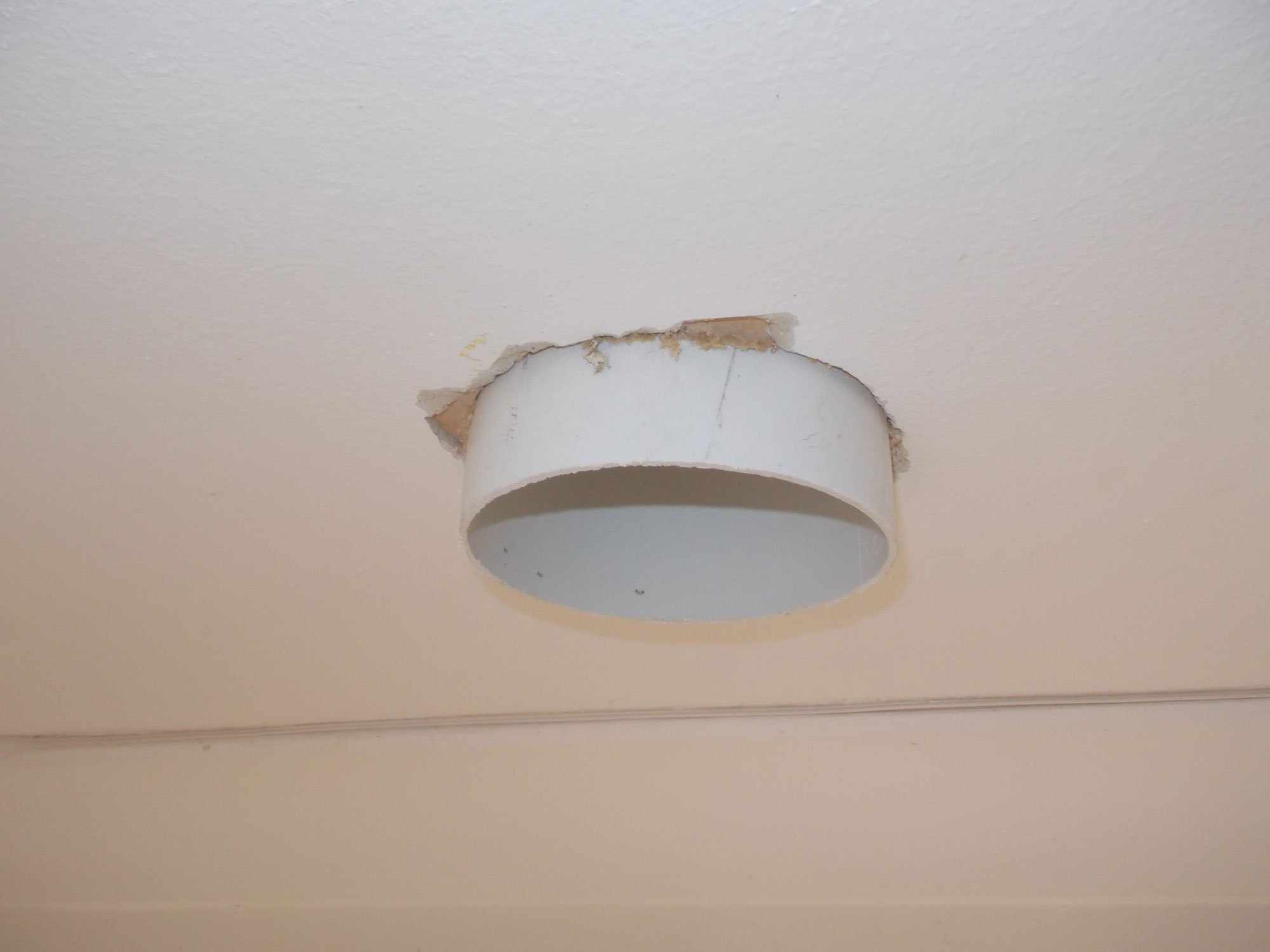
- Here is the outlet, exterior end, and as you can see it is somewhat longer than inlet end and protrudes further out from below the board.
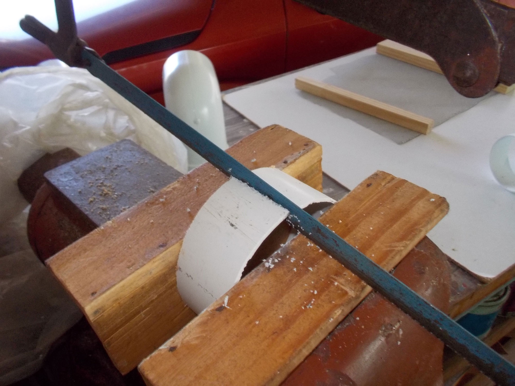
- The above were dry fittings. So with them still in place, I measured the distance between the ends of the bends, ensuring that I allowed for a proper seating between the connecting pipe and the bends, and cut the pipe to length. In passing cut it too long initially if in you are in any doubt as to the required length, and then trim it until you achieve the fit you need. Then remove the bends, slip them on to the connecting pipe and by resting the assembly on a flat surface, align the bends, as shown here.
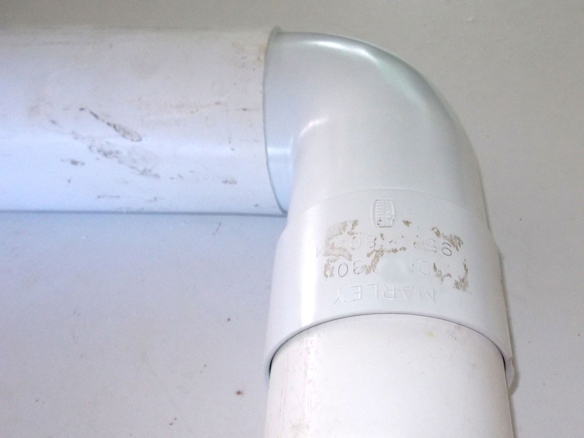
- This shows a close-up of the connecting pipe on the bend, with a short length of pipe that will pass through the ceiling board.
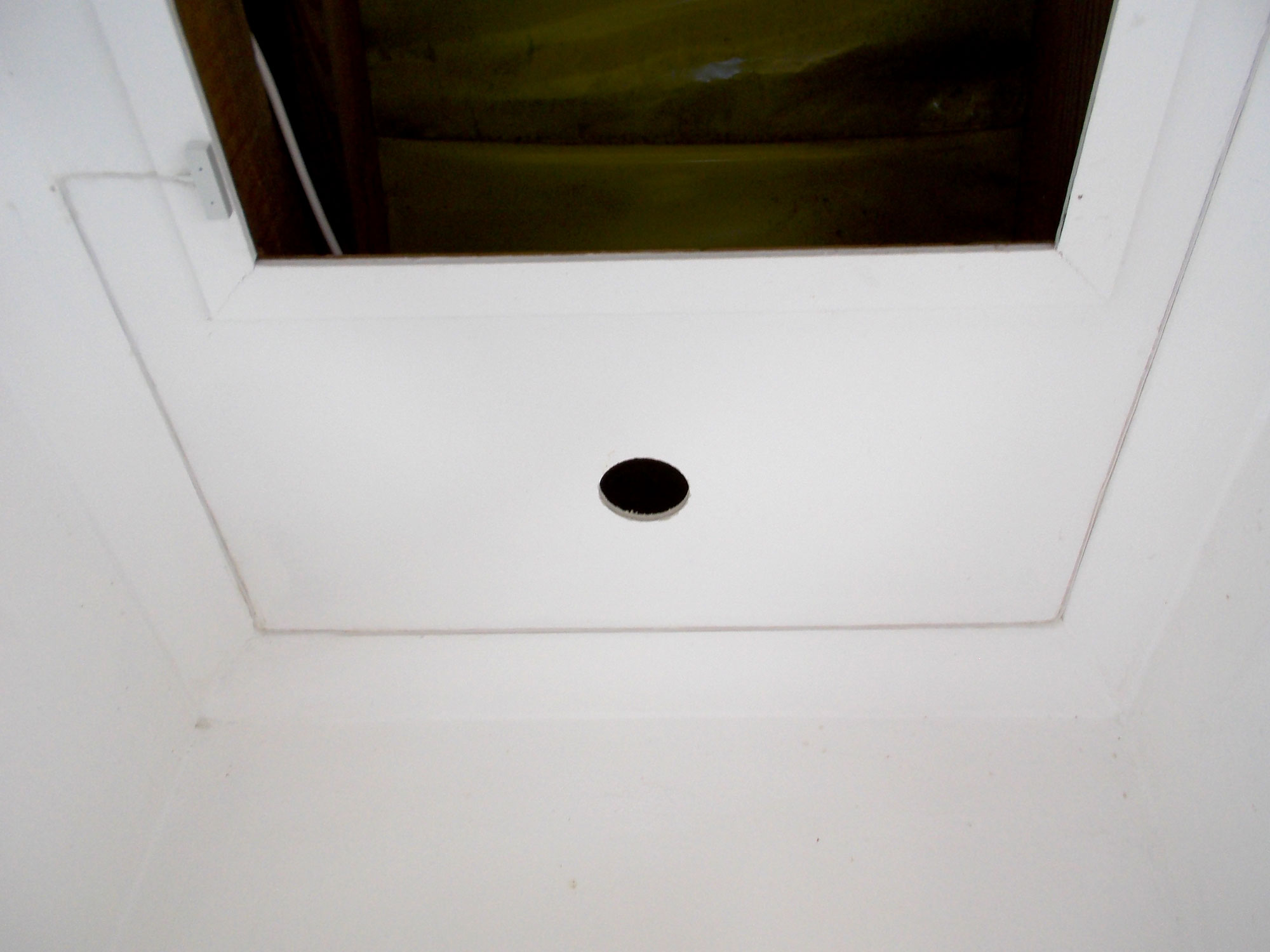
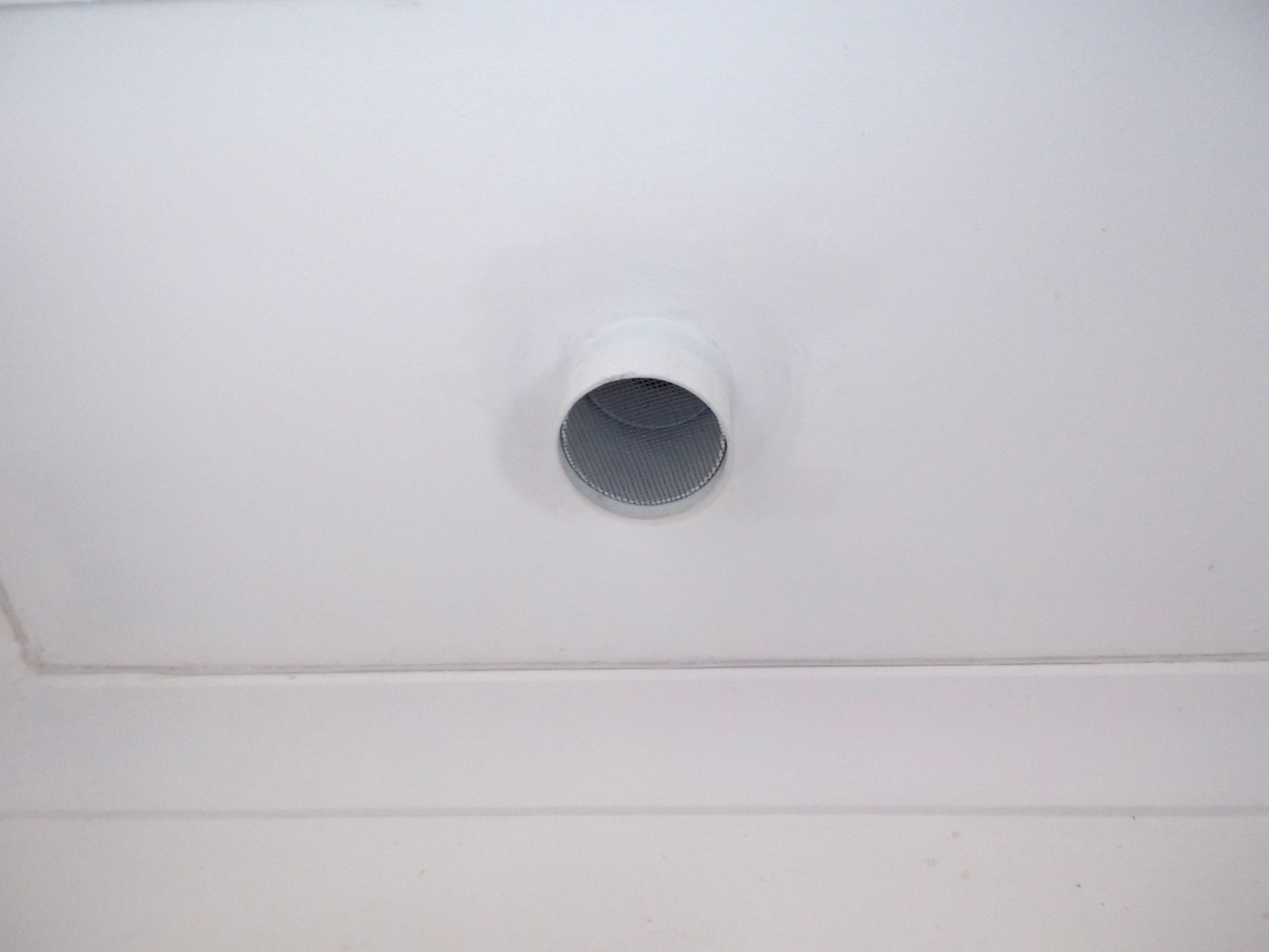
- With the assembly in position, I filled in around the inlet (interior) pipe to neaten the surface. You will also note that I have slipped a socket over the end of the pipe and used it to secure a fine mesh screen. I included the mesh to prevent the entry of insects and even larger intruders such as geckos.
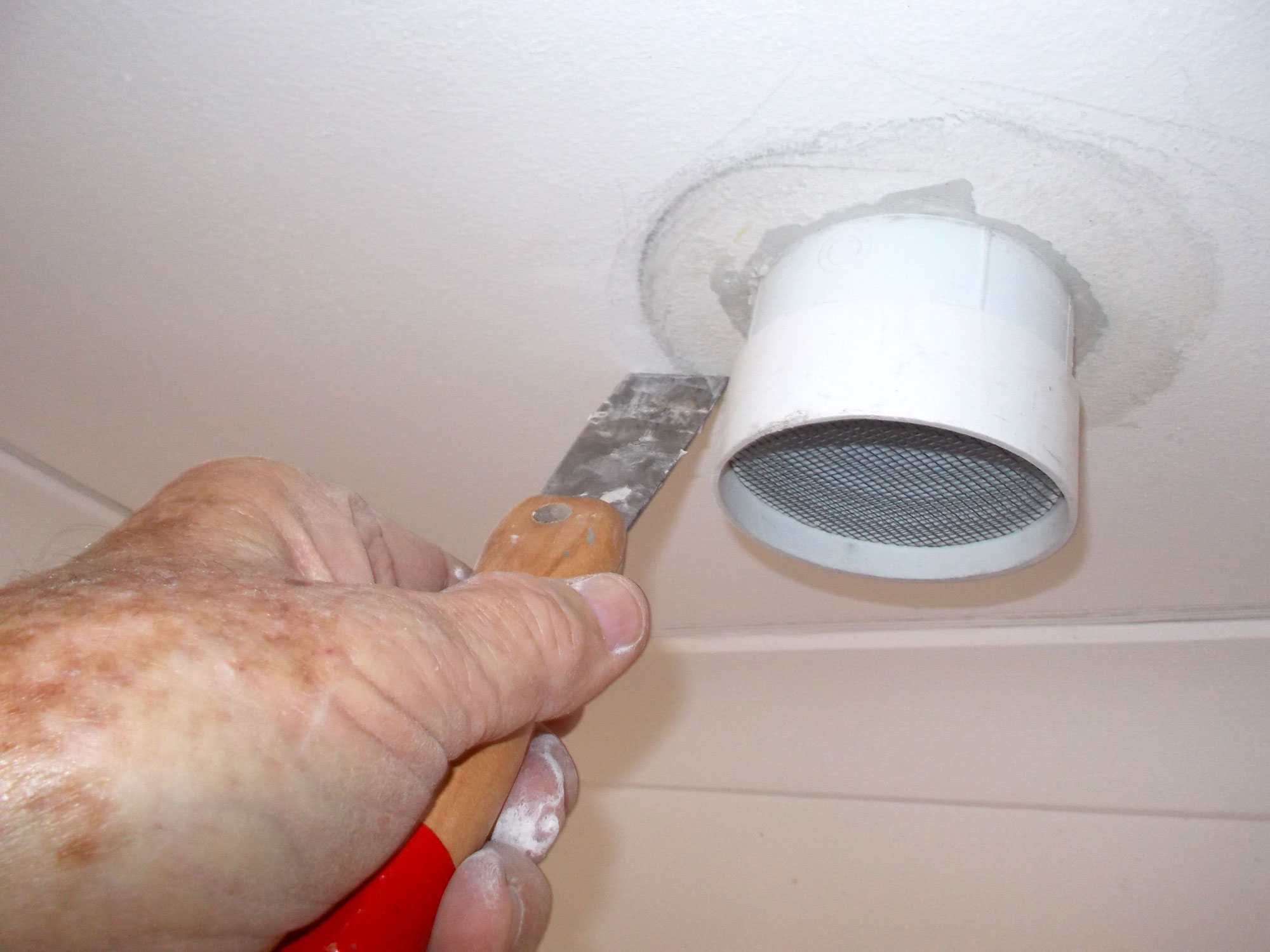
- Once the filler had set, I painted around the inlet hole to complete that end of the flue. A pretty neat result even if I say so myself.
- I was going to use a split pipe at each end of the flue to secure the mesh in position, but decided against it after all as I didn’t like how it looked. You, however, could use this method as it allows you to avoid the cost of the sockets.
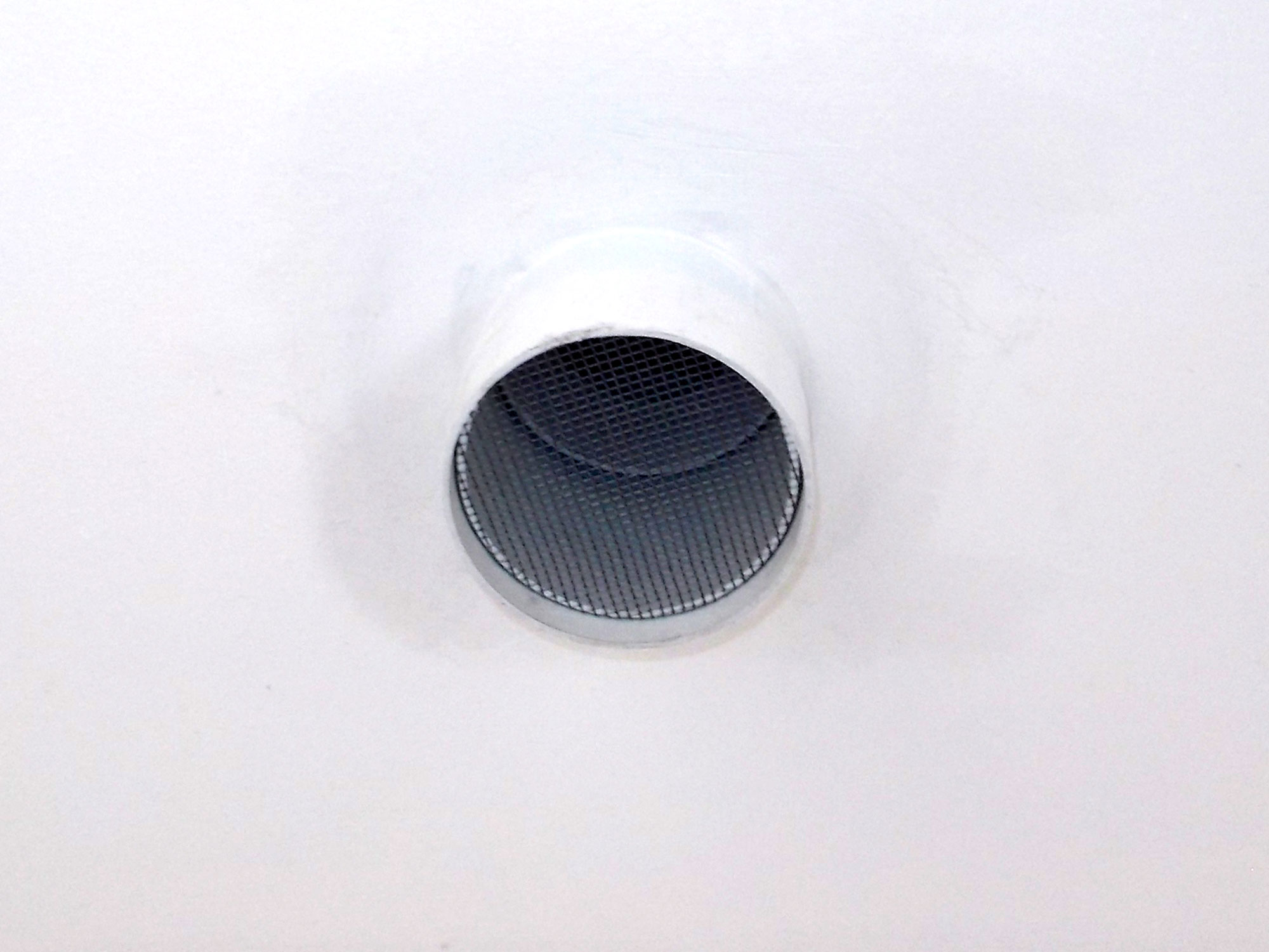
- This shows a close-up of the inlet end of the flue.
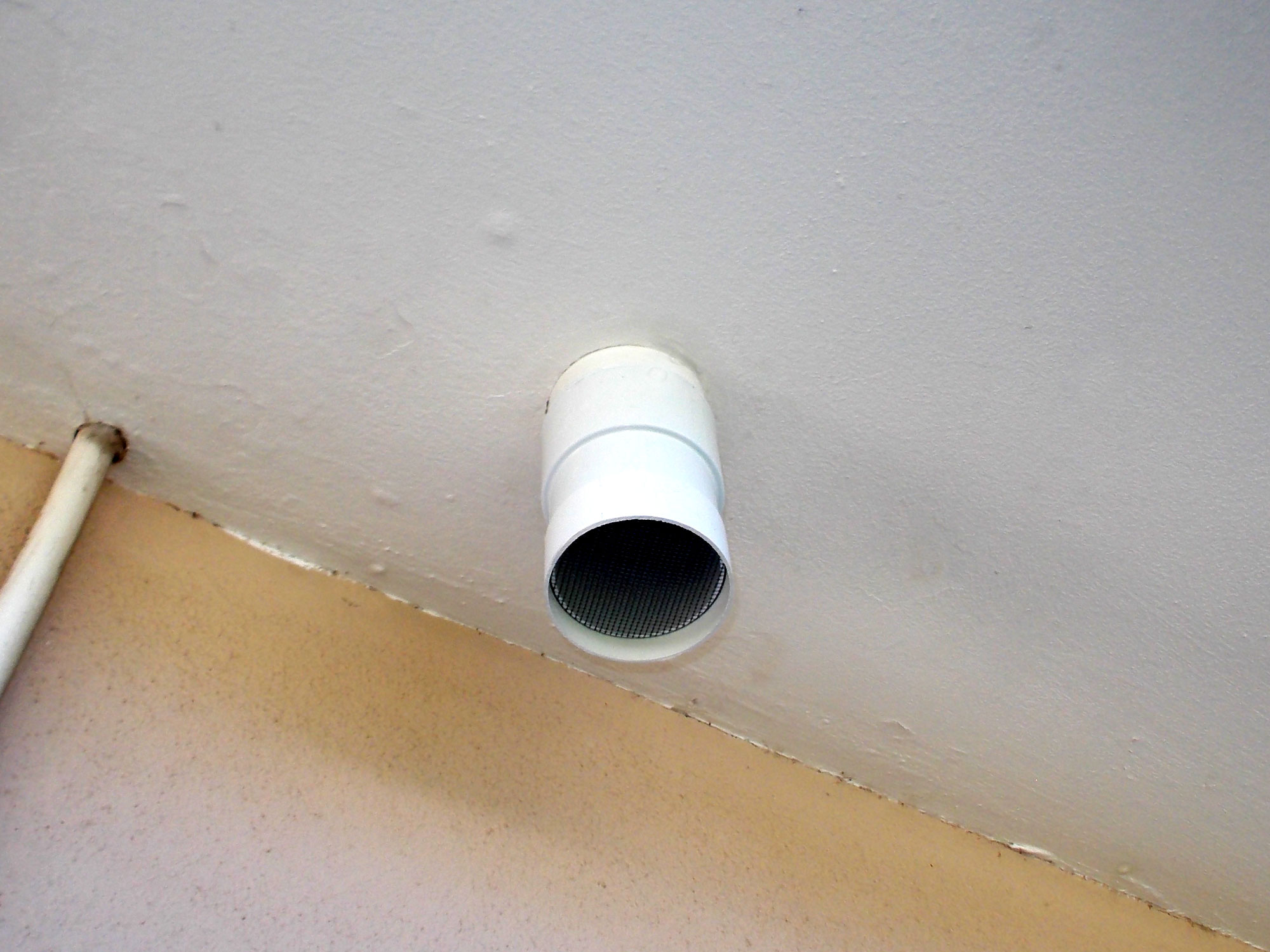
- And here is the exterior (outlet) end, finished off in the same was as I finished the inlet end. As you can see, this end of the flue is a lot longer than the inlet end. Also note that I use the second socket to secure a second mesh barrier.
- This illustration shows how the whole system comes together. Note the prevailing winds, which blow along the wall, obviously, will draw air out of the flue.
- And here is the complete system with the inverter installed. It is off-set to the left to accommodate a surge protection panel (not visible) on its right. You will also notice that it is installed quite high on the wall to keep trunking and wiring to a minimum and put it on the same level as the batteries, which are also mounted quite high so that it is easier to check their levels and performance etc – which are indicated by diodes on their lower surface, and you do not want to have to grovel around on your hand and knees to see what is going on.
Panel:
These materials are available at Selected Mica Stores. To find your closest Mica and whether or not they stock the items required, please go to www.mica.co.za, find your store and call them. If your local Mica does not stock exactly what you need they will be able to order it for you or suggest an alternative product or a reputable source.
Project guide
- TIME: One day
- COST: R50-R75.
- Skill: 2
- Assistant: No
Tools required:
Hacksaw, or jigsaw, rasp, spatula, cordless drill/driver with holesaw of required diameter fitted