05 March 2025

MICA – ADAPT-A-DRAWER
The idea behind this adaption was to take the existing pair of drawers, which were sticking on their drawer runners, and use the drawer carcasses themselves as the mounting units for a pair of slightly narrower and shallower drawers in each.
Then both of the existing drawers would be fixed back into place in the kitchen cabinet body (with some support members and adjustments made to each) and then the 4 new drawers – 2 per existing drawer becoming the working drawers.
Clear as mud?
Don’t worry, it will become very clear as you work read through the feature and view the images.
And regarding the images…
A note about colour under different light levels etc
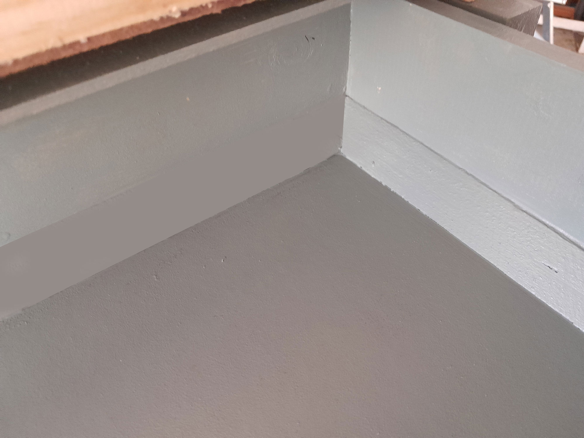
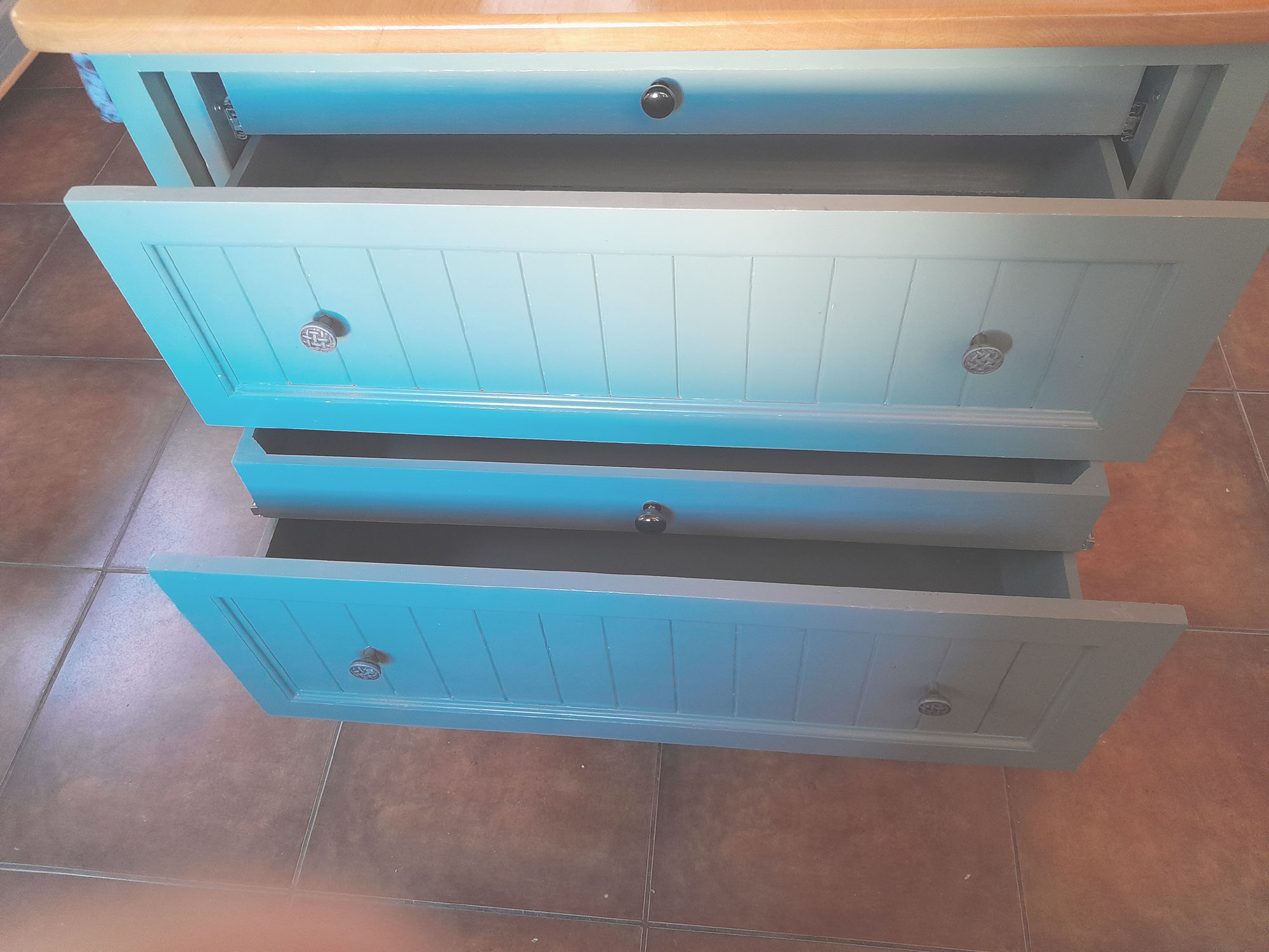
When you look at the colour of the drawers, facades and so on you will notice that the images of the final result seem to show the surfaces have been repainted in a bluish tone.
They have not. There has been not change whatsoever to the drawers and kitchen cabinet colour. It is simply a trick of the light.
The before image of the cabinet, with a single drawer in front of it, was taken in the morning. The step-by-step images were taken at various times of the day, but usually morning/midday/ very early afternoon. Hence all these images show the colour as it is … a rather attractive lead-grey hue.
The final shots were taken in the very late afternoon, and with the sun at a far shallower elevation, there was more reflected light off various surfaces, and so on. Hence the colour appears to have changed to a bluish hue.
I left it like that as an object lesson in paint selection: When selecting a new colour, buy a test pot and paint a piece of hardboard or similar and then view the colour in different lights – ambient, and artificial.
You will very likely notice that the surface has a different appearance under different light conditions, shadows, reflected light off other surfaces and so on. Using a colour swatch is great for your initial choice, but to really appreciate how a particular paint’s colour can appear different to the eye under different conditions, it is best to use a large – I suggest at least 300x300mm – sheet of wood or hardboard to give you the best appreciation of the colour’s changing appearance.
A note about drawer depths
The existing drawers that were jamming were 250mm deep, which is a an excellent depth for a drawer used for winter woollies, clothing, blankets and that sort of thing as they are quite light but take up volume.
In a kitchen drawer, however, 250mm deep could be a tad deep, with the user finding it a bit of a challenge to make full use of the capacity, and in trying to do so, possibly overloading the drawer itself, and/or the drawer runners/runners or whatever.
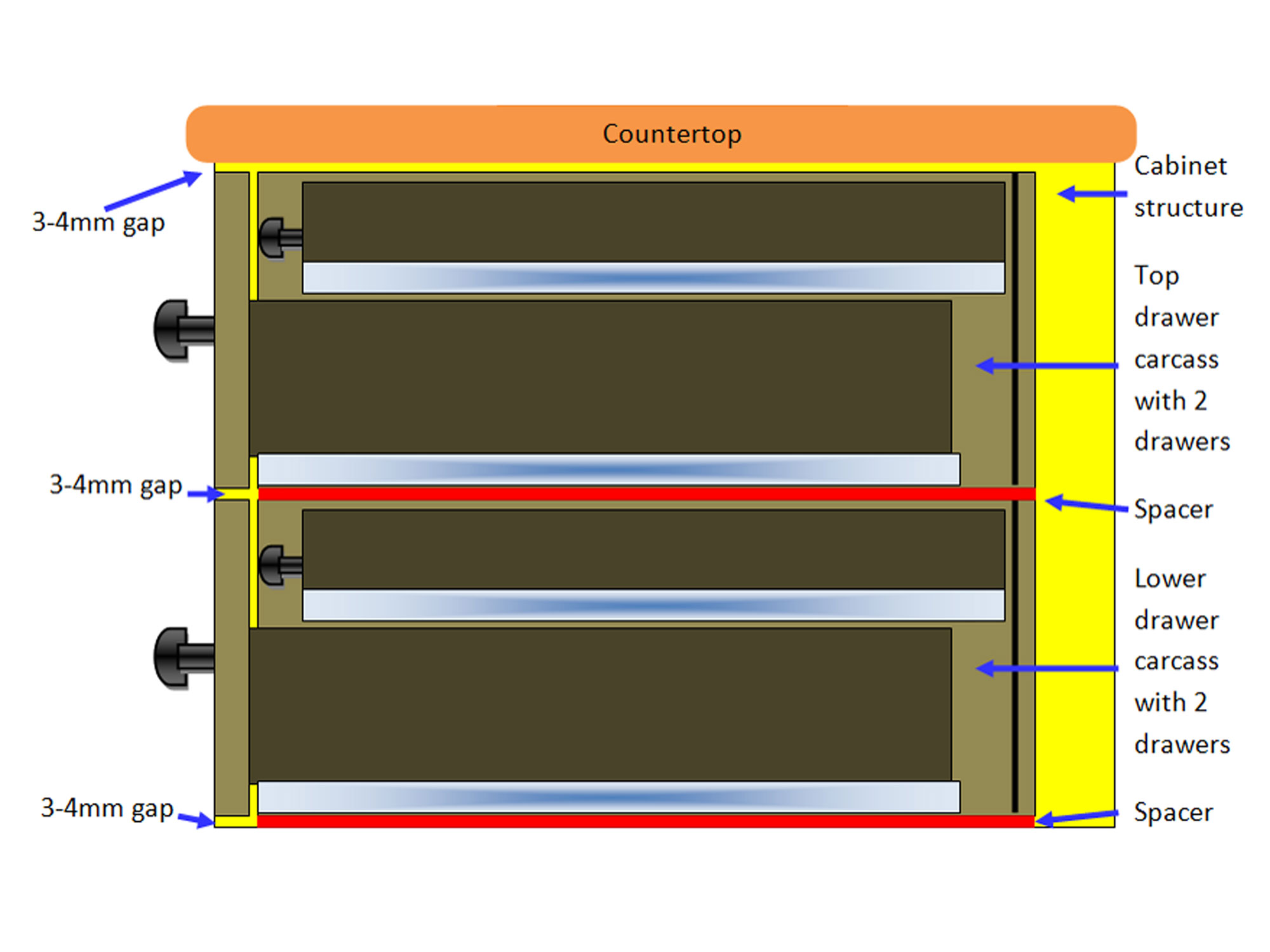
The existing open space in the kitchen cabinet into which the drawers were fitted measured 945mm wide x 640mm high x 475mm deep.
And those dimensions determined EVERYTHING!
The new work had to ensure that no changes would be required for the kitchen cabinet structure, other than supports being attached where necessary.
The overall aim was to increase the storage area and reuse the existing drawer fronts so that the adaption would not change the overall appearance one bit.
It worked!
And this is how I went about it…
Materials:
The materials will vary according to the specifics of the drawers you might like to use for this adaptation, so the list given here is for this set only, and is very unlikely to apply in any other case, but is for guidance only…
- SA pine – par
- 12×144 – 3 lengths of 1.8m
- 12×96 – 3 lengths of 1.8m
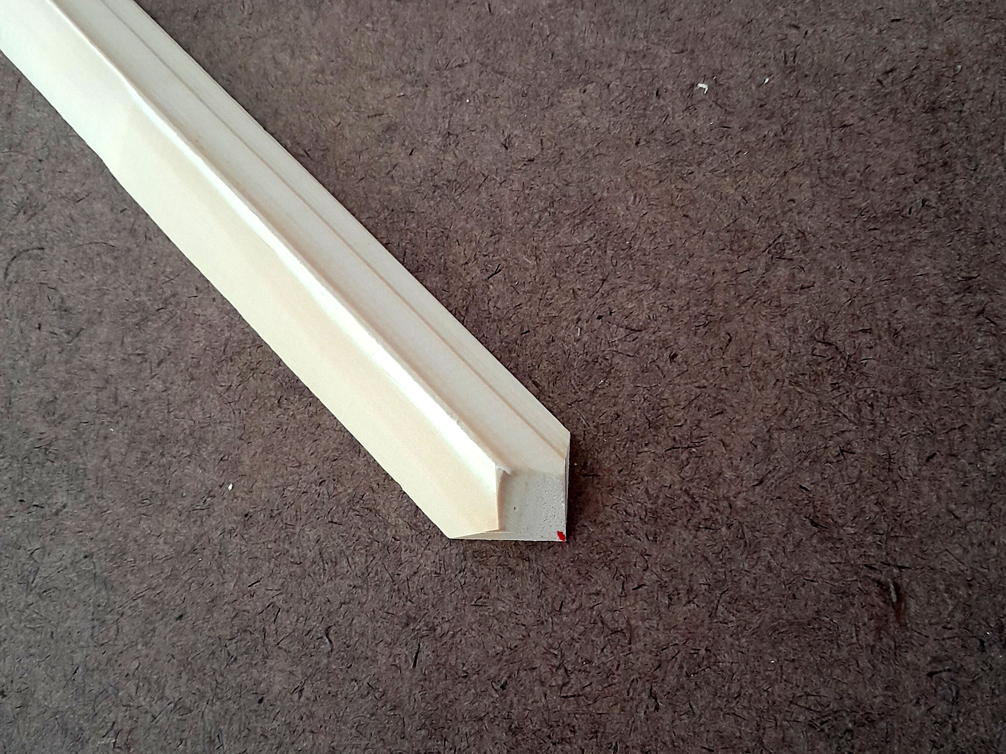
- SA pine 22x22mm chamfer moulding – 3-4 lengths of 1.8m
- Masonite (tempered hardboard) – 3.2mm – 1 full sheet
- Drawer runners – 35kg capacity – 350mm long – 4 sets
- Screws
- Drawer fixing screws – 100 of 30mmx4 gauge
- Drawer runners attachment screws – 50 of 12mm
- Drawer carcass corner reinforcement screws and fixing screws – 35 of 40mmx8 gauge
- Panel pins – 1 pack of 32mm to reinforce the drawer front corner attachments
- Wood glue
- Wood filler
- Matching paint – 1 litre can
- Drawer knobs – 2 (the 4 existing knobs would be used back on the frontages, just as they were originally.
Method:
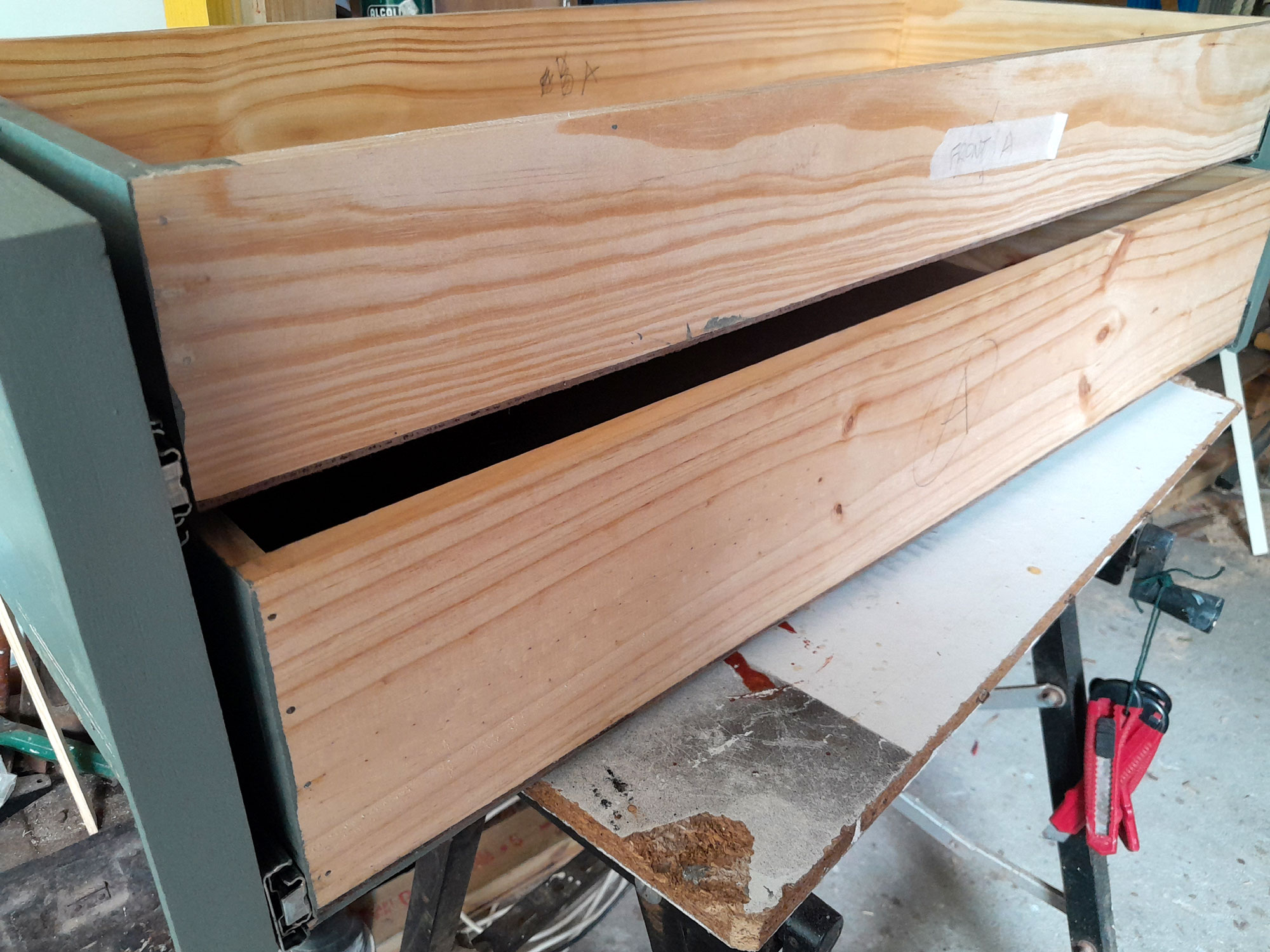
- One of the existing drawers. The contractor who did the original work did a very good job but due to time and wear and tear, the drawers began to jam and scrape on each other. So…
- I thought of a solution based on one of my original ideas, which raised my stocks with The Boss, The Big Cheese, SWMBO (She Who Must Be Obeyed) big time… sliding shallow trays. They have made our lives immeasurably easier. So this is what I came up with…
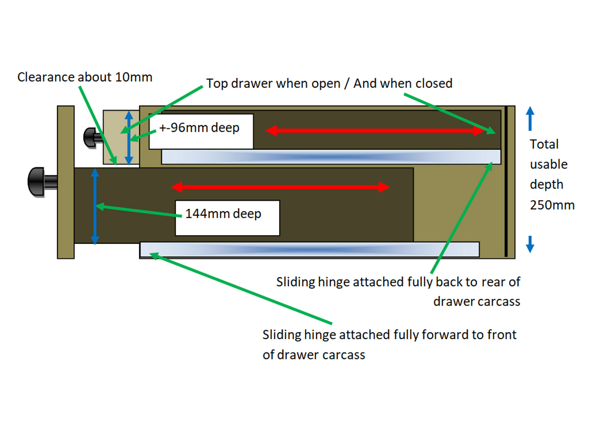
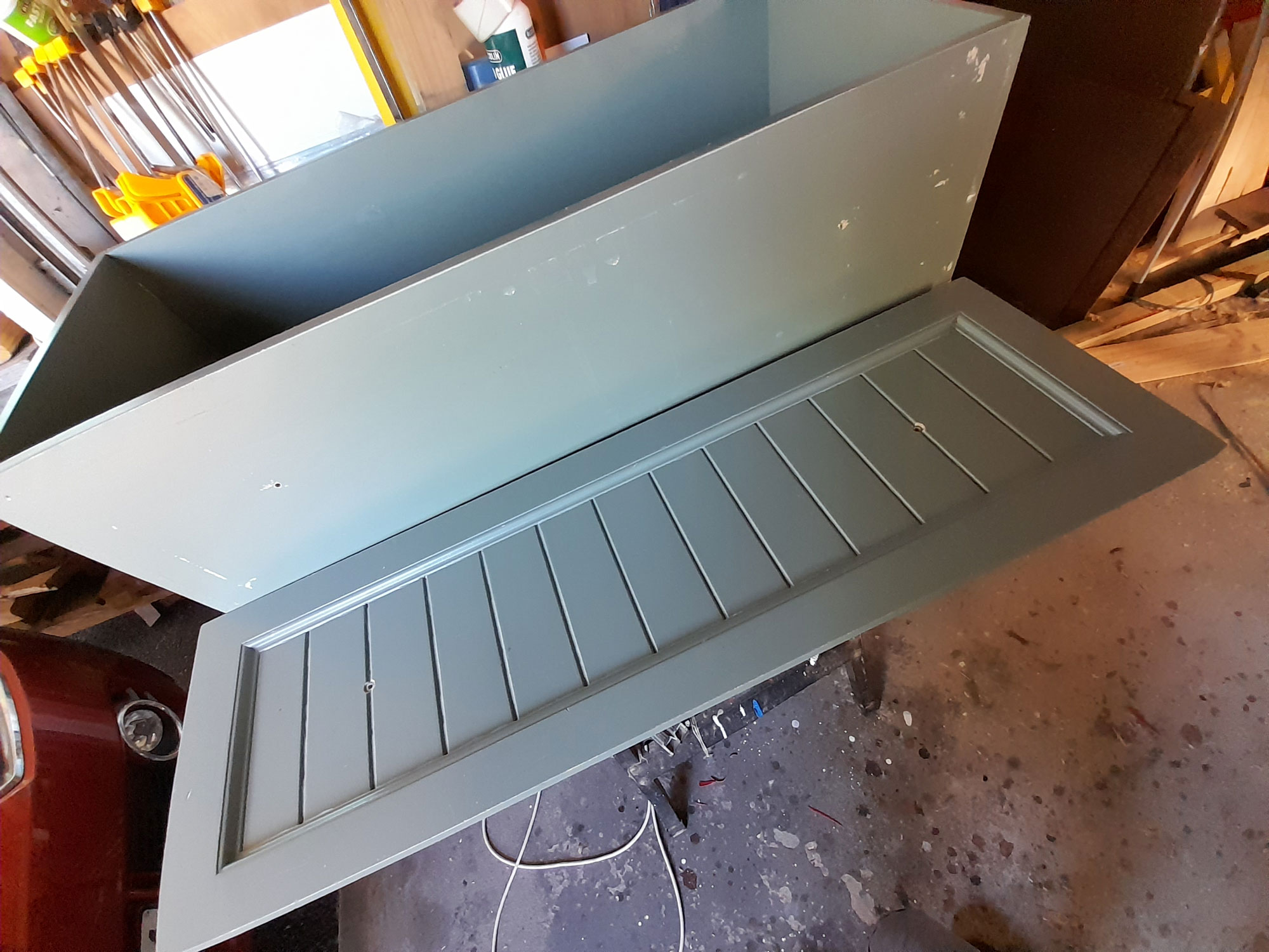
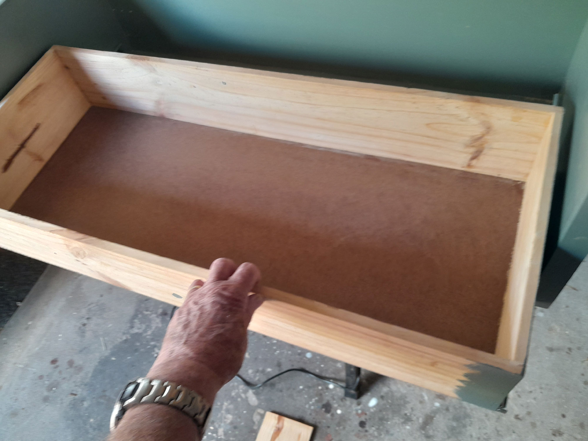
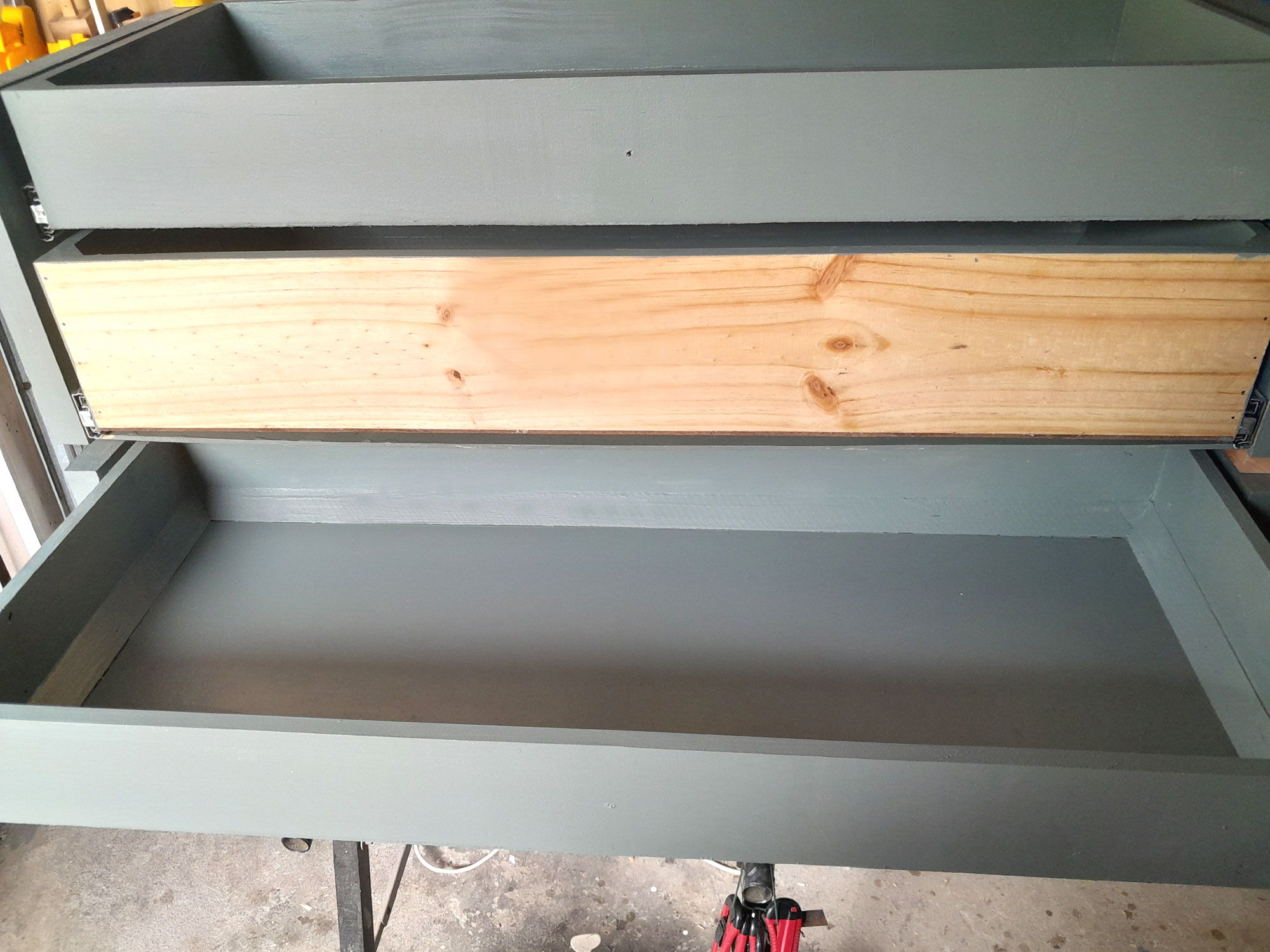
- With the front of the façade of the existing drawer removed, and then also the front panel of the existing drawer, I would end up with an open-fronted box, into which I could mount 2 shallower, marginally narrower and marginally less deep drawers. So there would be some volume sacrifice per drawer, but as a pair, both would offer almost double the storage area – note, I say area, NOT depth. But with the lower with a depth of +-145mm, and the upper with a depth of +-96mm, there would be ample space for most kitchen items, spaces, canned foods, and cutlery and so on.
- And this is how the pair of existing drawers, now fixed in position, would become the mounts for the 4 new drawers. The existing facades would be attached to the new lower drawers, with the new upper drawers being set back just over 30mm, as you can see from both illustrations.
- First step was to detach the façade from each drawer. I began by removing the drawer knobs, which would be refitted at the end of the adaption.


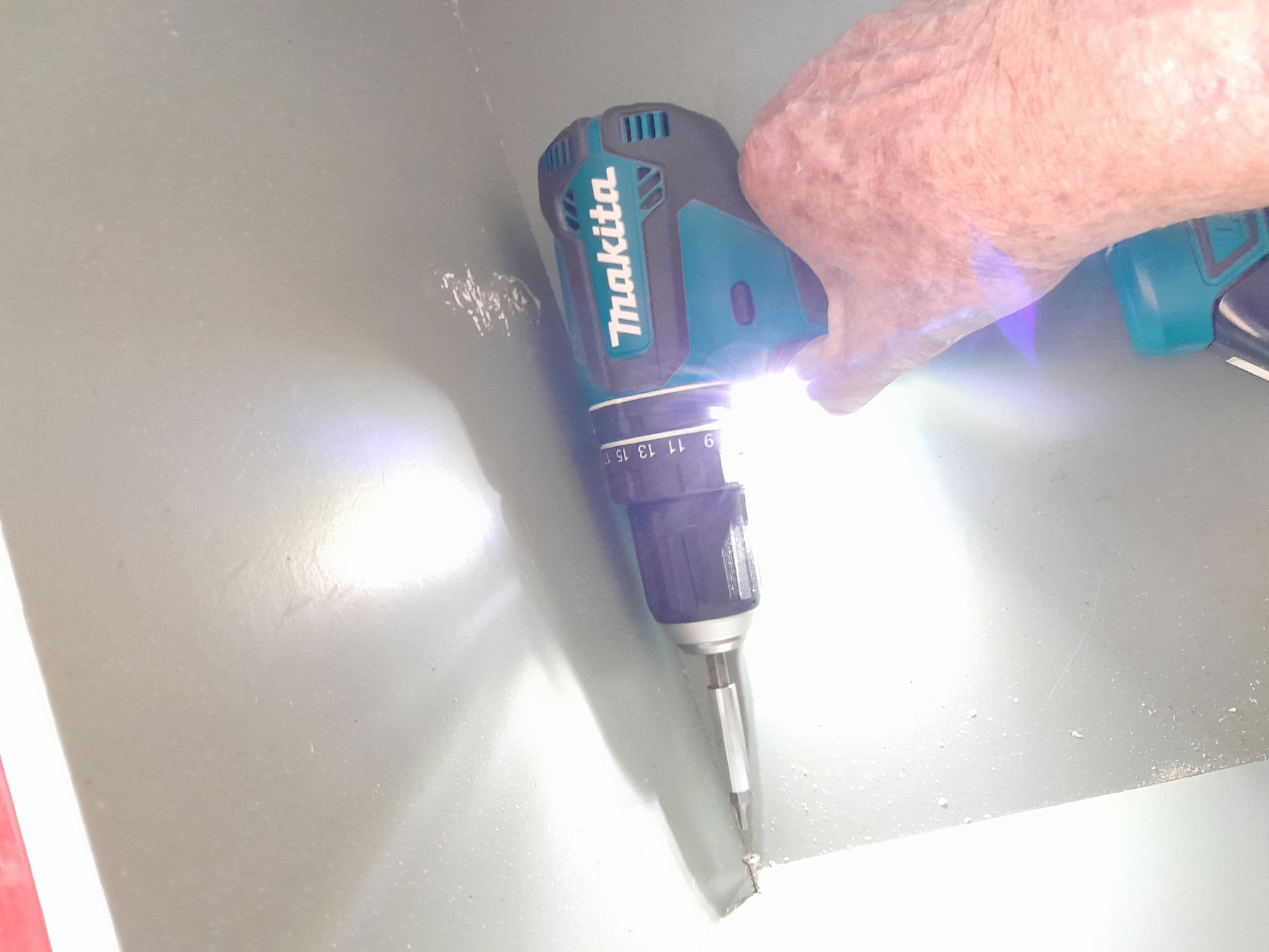
- Then I removed the 4 securing screws.
- And here is one of the facades, face-up, in front of its drawer body.
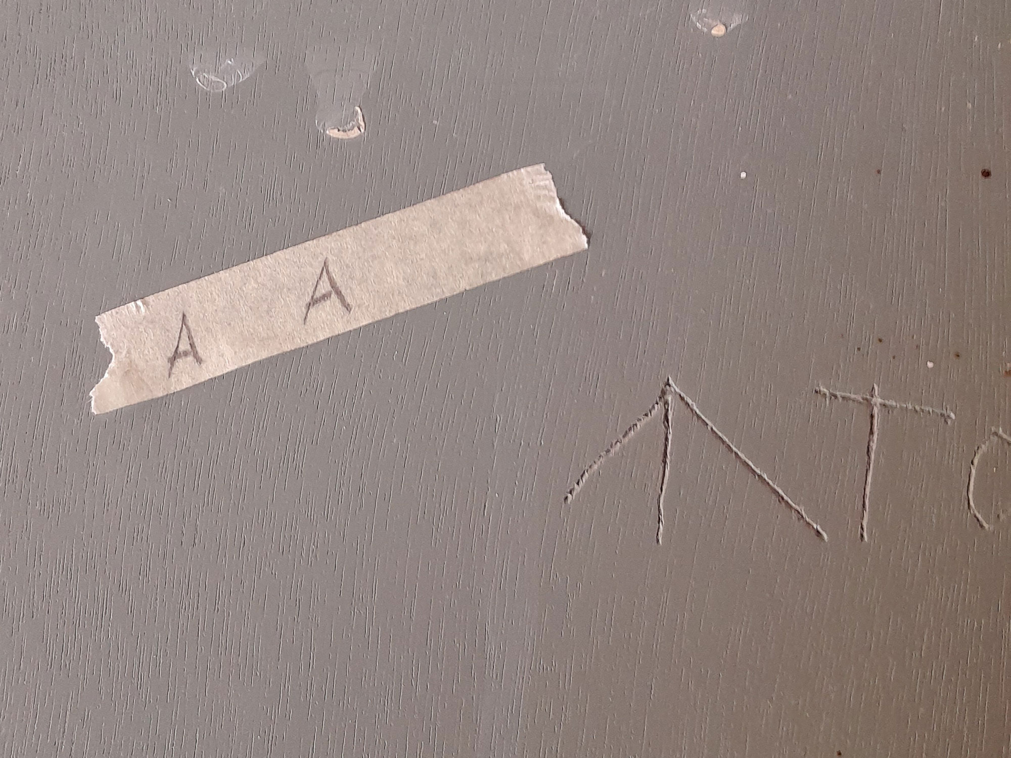
- I used tape to keep track of which façade came off which drawer and that corresponded to their positions in the kitchen cabinet… ‘A’ being the top original drawer, and ‘B’ being the lower. Given the fact that the original fitting was made to close tolerances, I wanted to ensure as close a fit to the original as possible.
- On thinking about it, tape could be a bit problematical if it comes off, so you can back it up with or substitute for a permanent marker – naturally in a spot that will not be visible.
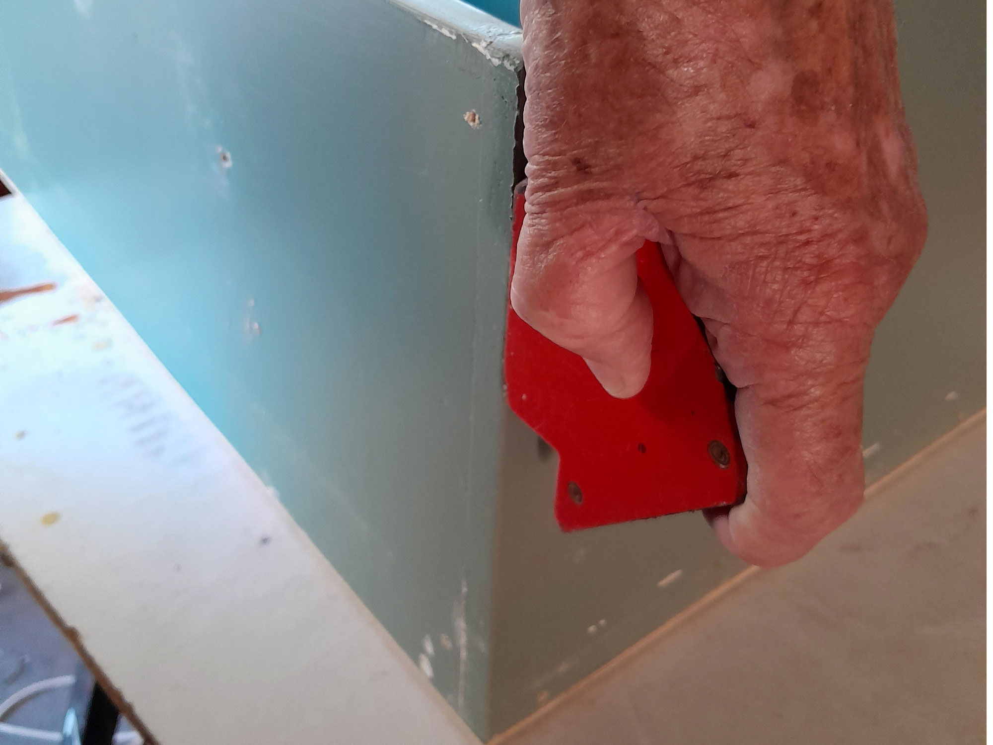
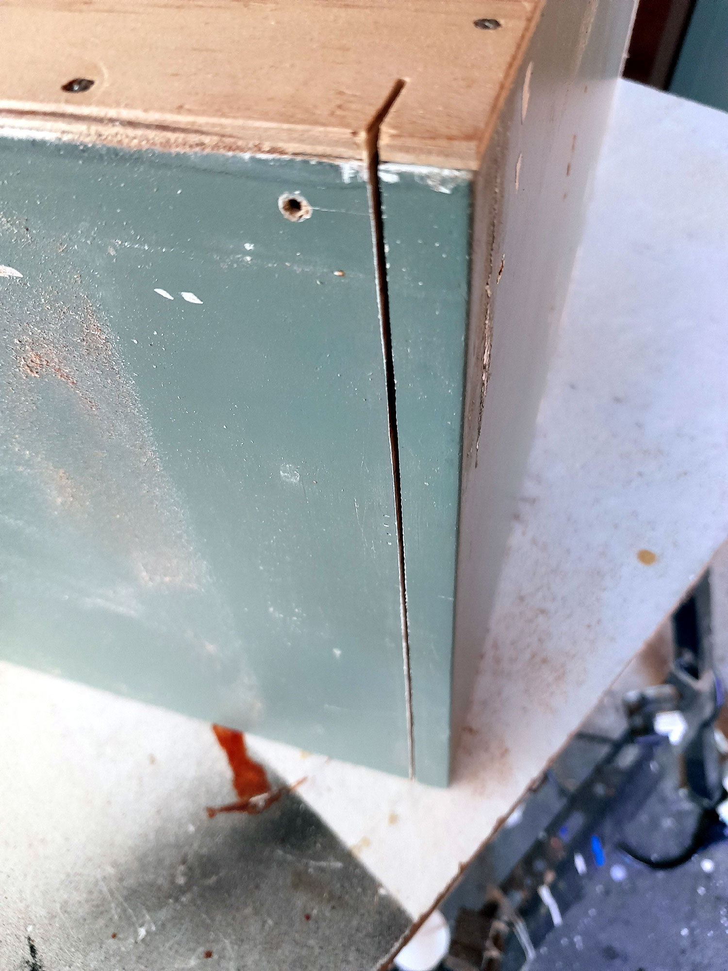
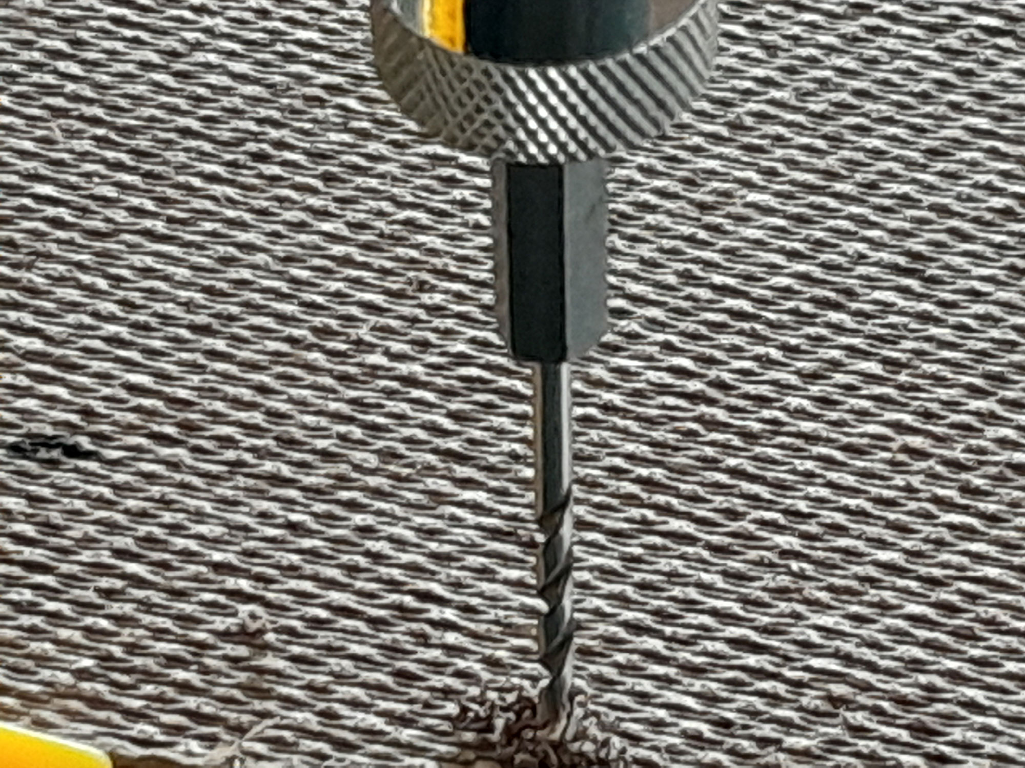
- Before cutting off the front of each drawer, I ran a strong magnet along the join to ensure no panel pins would be lurking in it to ruin my saw blade.

- Then I cut along one side at 13mm, then along the base and the other side, to remove the front.
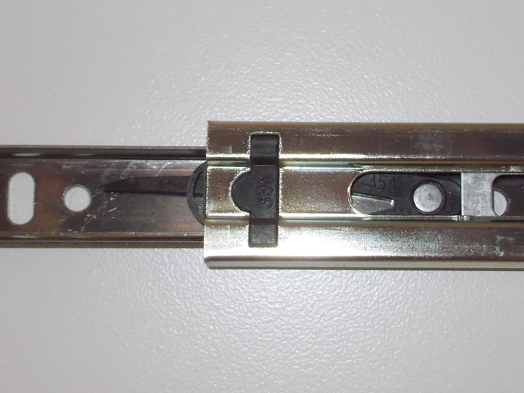
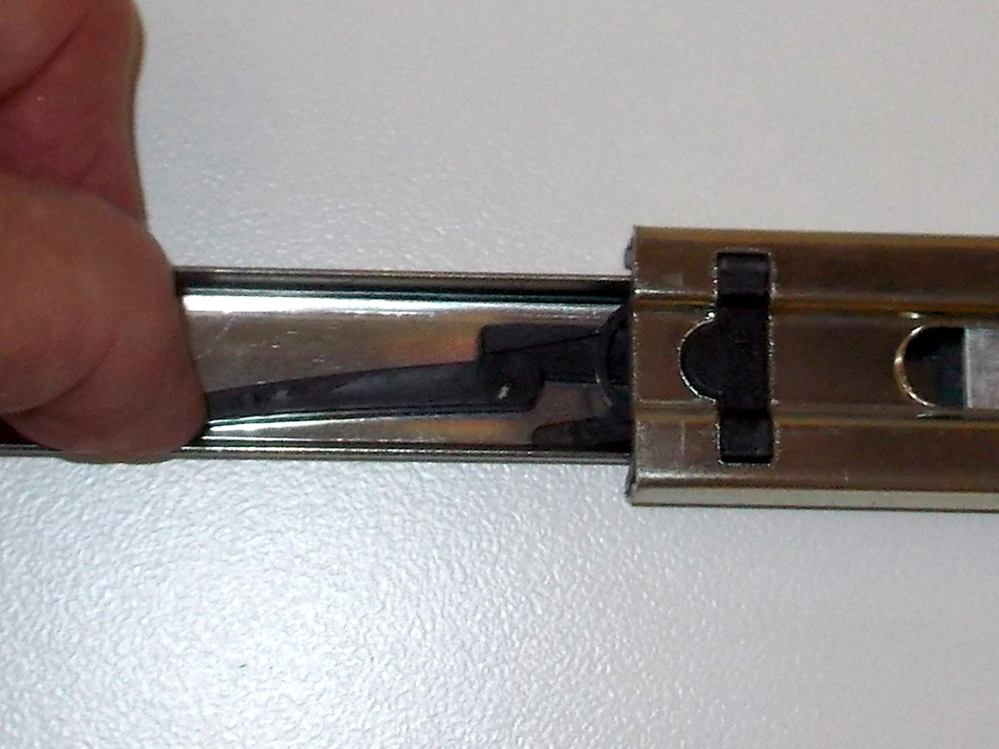
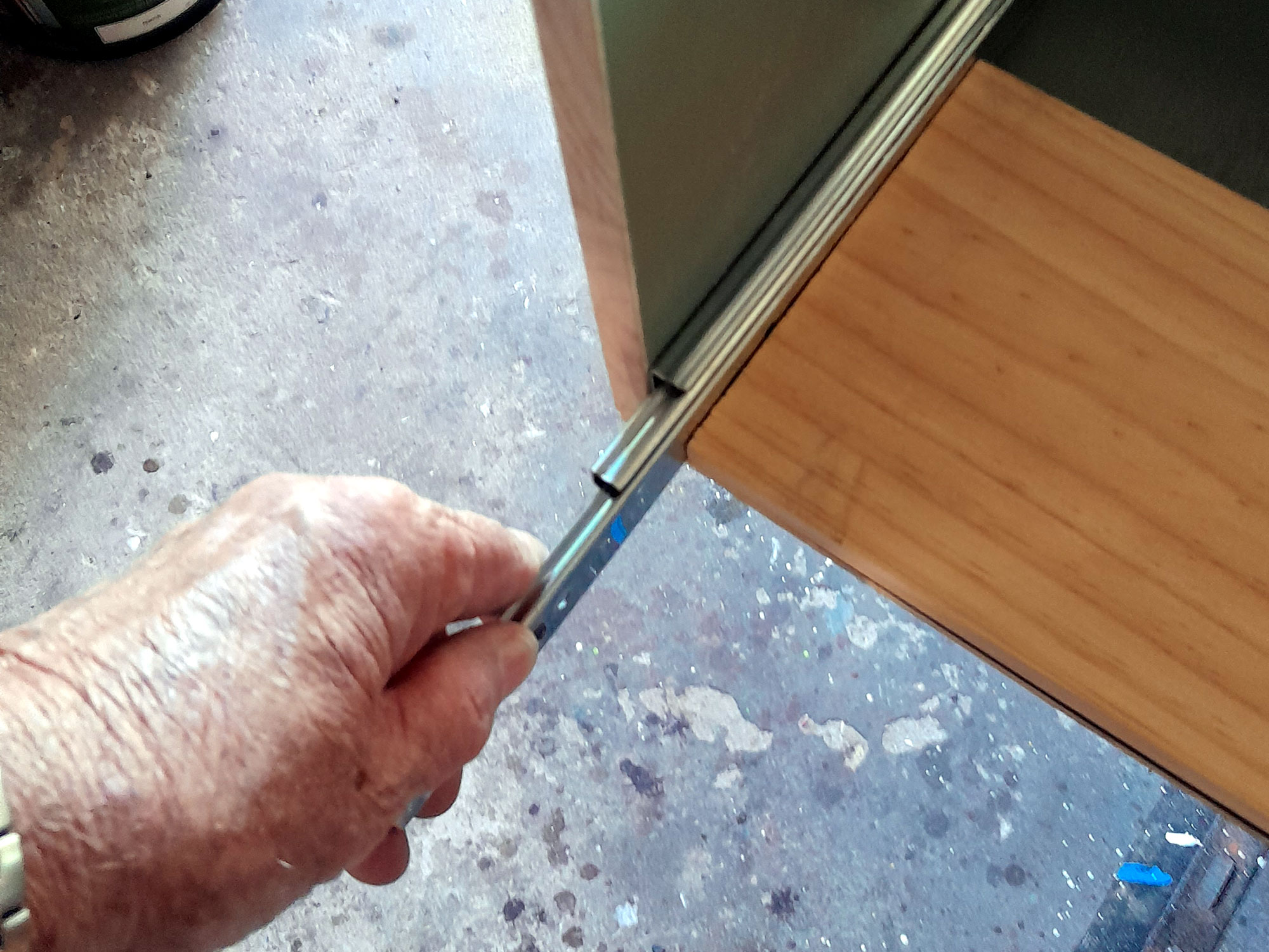
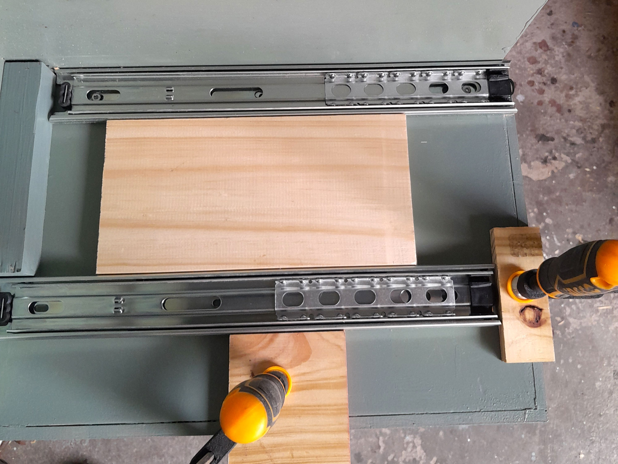
- Then I began attaching the runners to the first carcass. Bad move! As you will just below… before we go further, before fitting the runners, you will need to separate the fixed side – that which is attached to the frame, from the slider side – that to which is attached to the drawer. So, pull it open until a long black plastic lever becomes visible.
- With your finger, pull the end of that lever up, as shown here.
- Then you can remove the 2 parts of the runner from each other, as shown here… the lever’s purpose is to prevent the runners being over-extended and coming free.
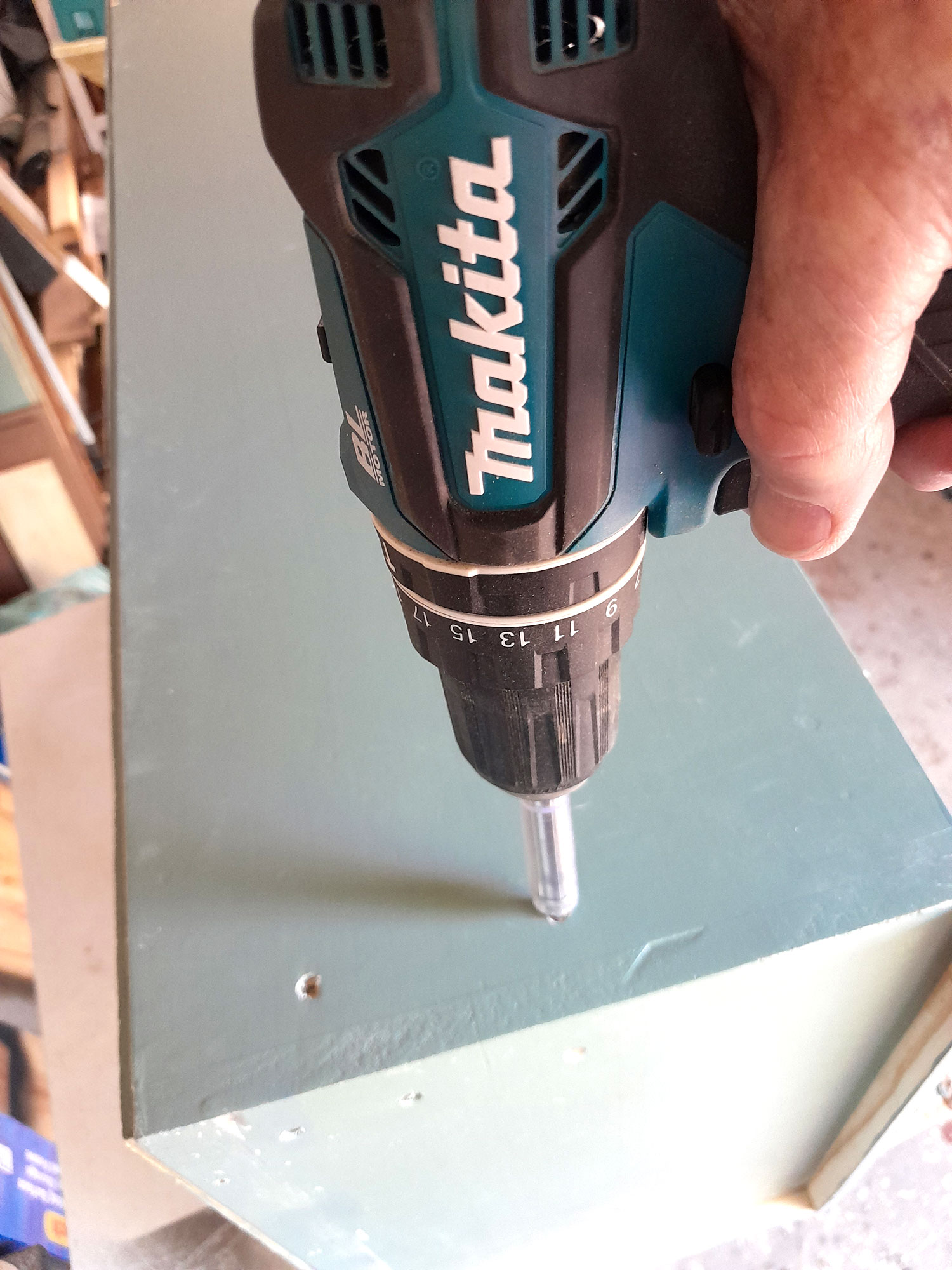
- So, I fitted the first runner base to the bottom of the side.

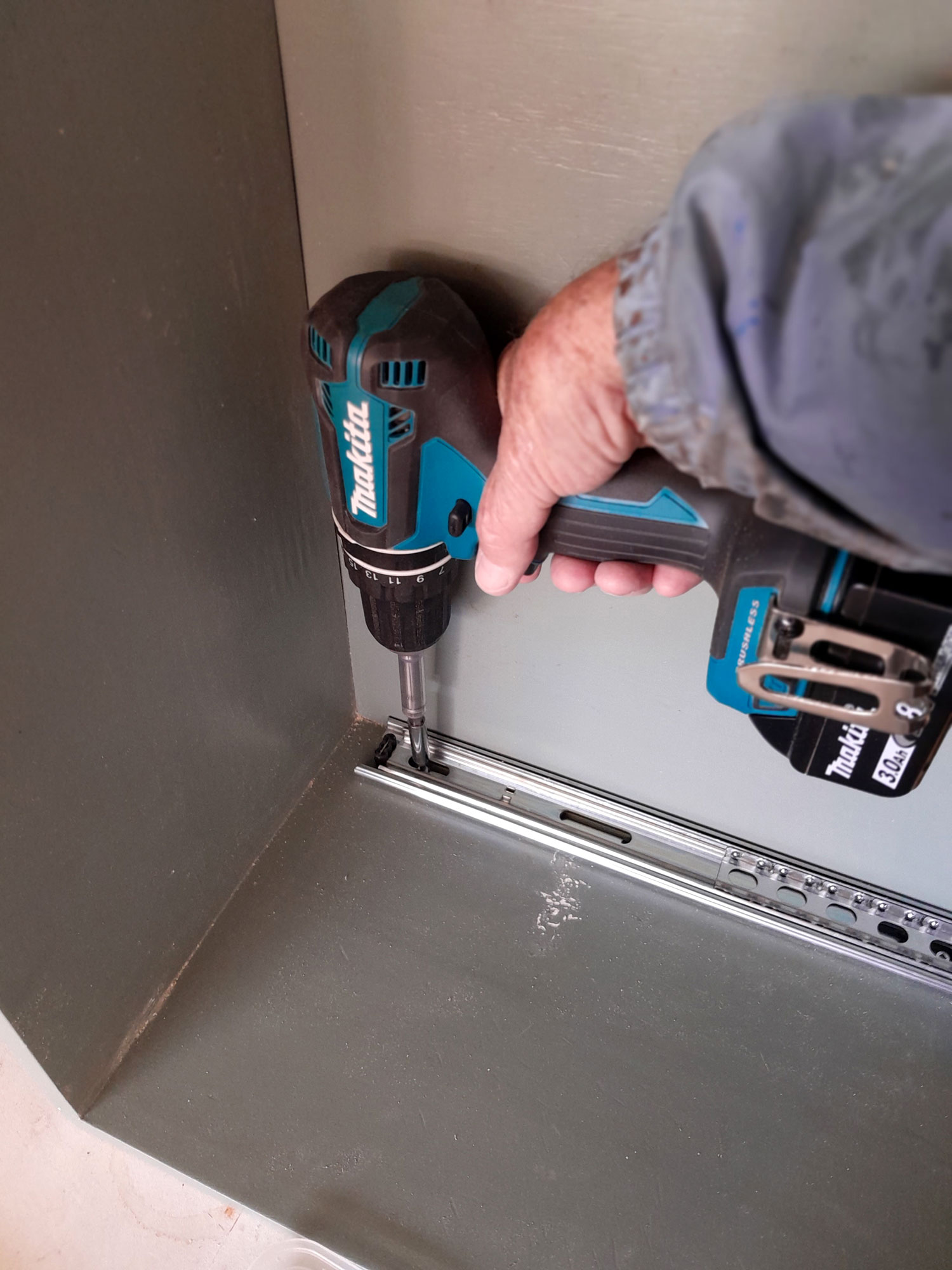
- As a general rule, I check for full and free movement as I drive in each attachment screw so that if there is a problem with one, I will know it was the last one and I can remove it and try again.
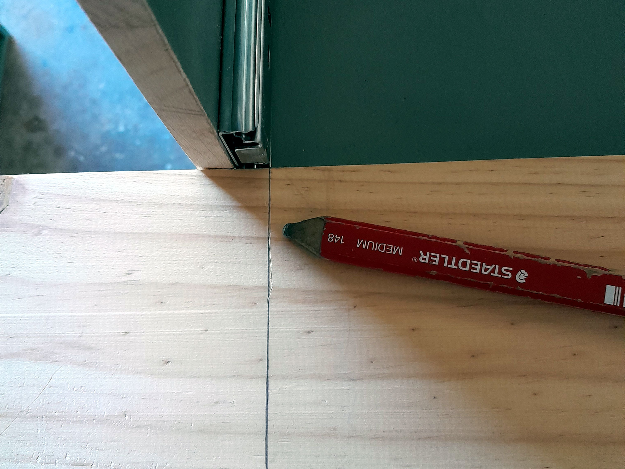
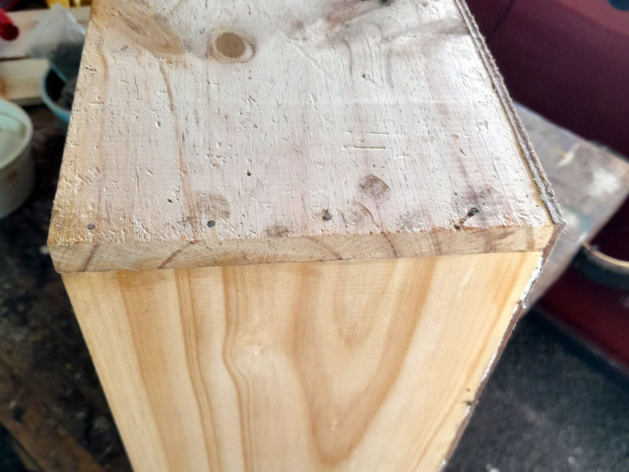
- Then I measured off the cut line for the new lower 144mm-deep drawer. Note that I used a utility knife for as very precise cut line and then highlighted in pencil.
- I cut the first piece to length and ensured it fitted, by checking for full and free movement of the runner. Trimmed off literally by the 0.5mm to reduce it to the correct length (which would of course be the full width of the drawer). Then I cut the second piece, using the first as the guide.
- Then I decided on a 9x44mm cover strip front to the carcass to close the gap between the kitchen cabinet structure and the carcass side. That is when I realised I had boobed…
- The leading edge of the runner would have to be flush with the front of the cover strip – which meant the runner would have to be moved forward 9mm. I said “Gosh!”


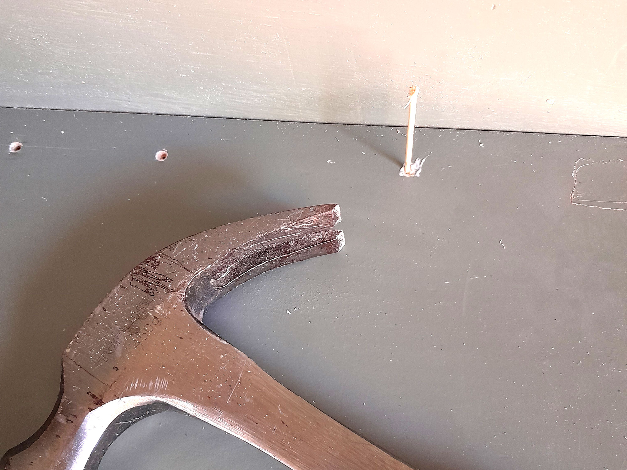
- I removed the 2 runners and filled their attachment screw position with toothpicks glued into position. I tapped home a number in each position to ensure a very tight fit.
- Like so. The excess is snapped off and any protruding ends cut down flush with a utility knife.
- Now I reset the runners, with their leading edge flush with the cover strip. The attachment screws were driven in as before, but obviously now offset from their original positions by 9mm. Filling their original positions, however, ensured that the wood in which they are now seated is fully supported and will not break away.
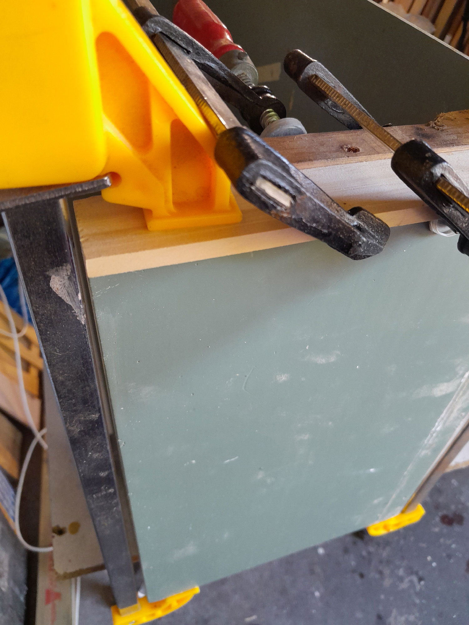
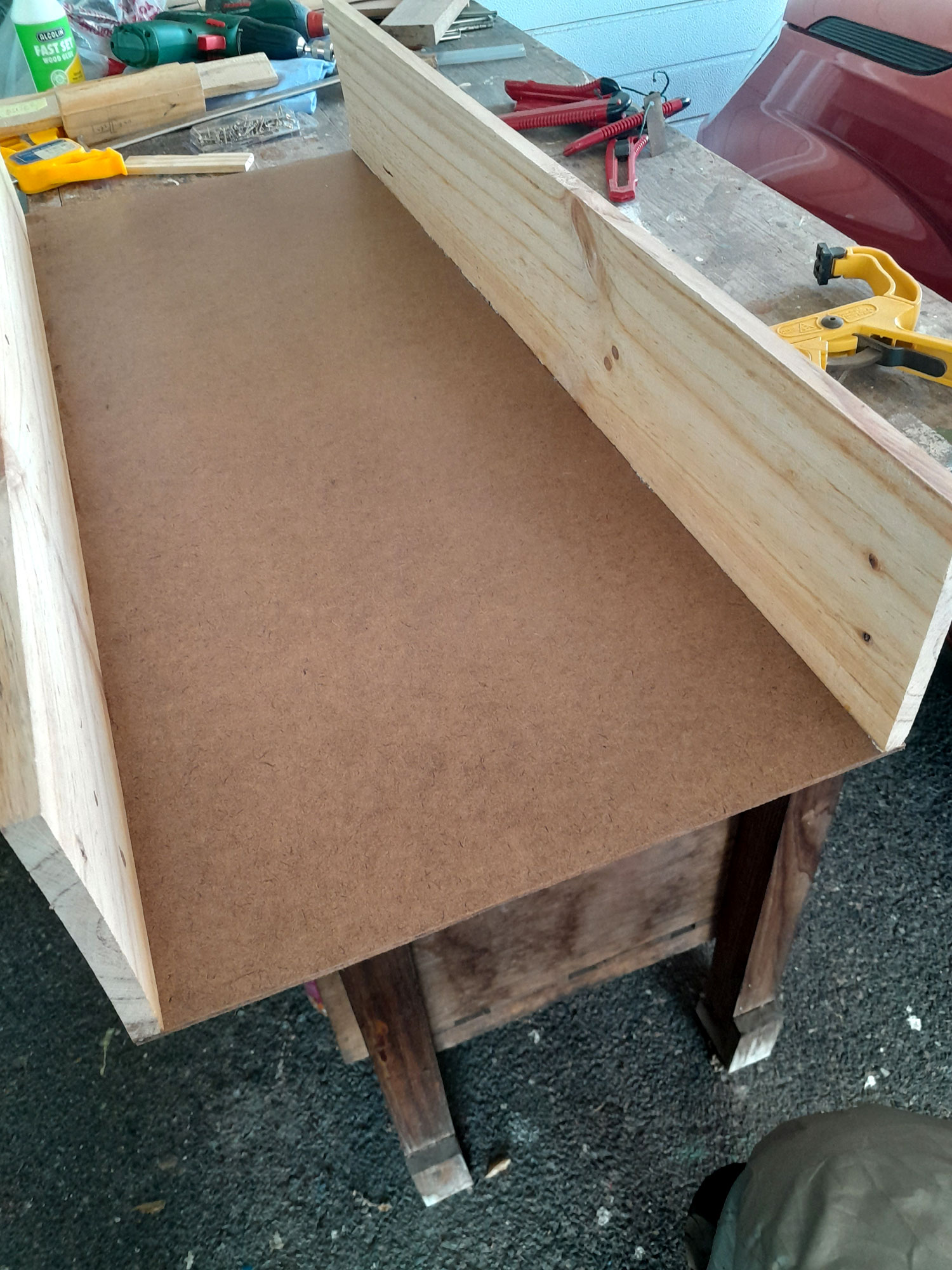
- Back to the drawer assembly… I cut the tempered hardboard base to size; in this case 350mm wide (to match the runners’ length, length as per the pre-cut drawer front and rear panels. Then I clamped one panel between 2 uprights to keep it steady and vertical.
- With glue applied and the first panel firmly clamped on to the leading edge of the base I secured the front to the base with 30mm screws at approximately 70mm intervals, the 2 on each end being about 30mm in from the end.

- Then I turned the assembly around 180º and fixed the other panel to the base, again using glue and screws to secure the join.
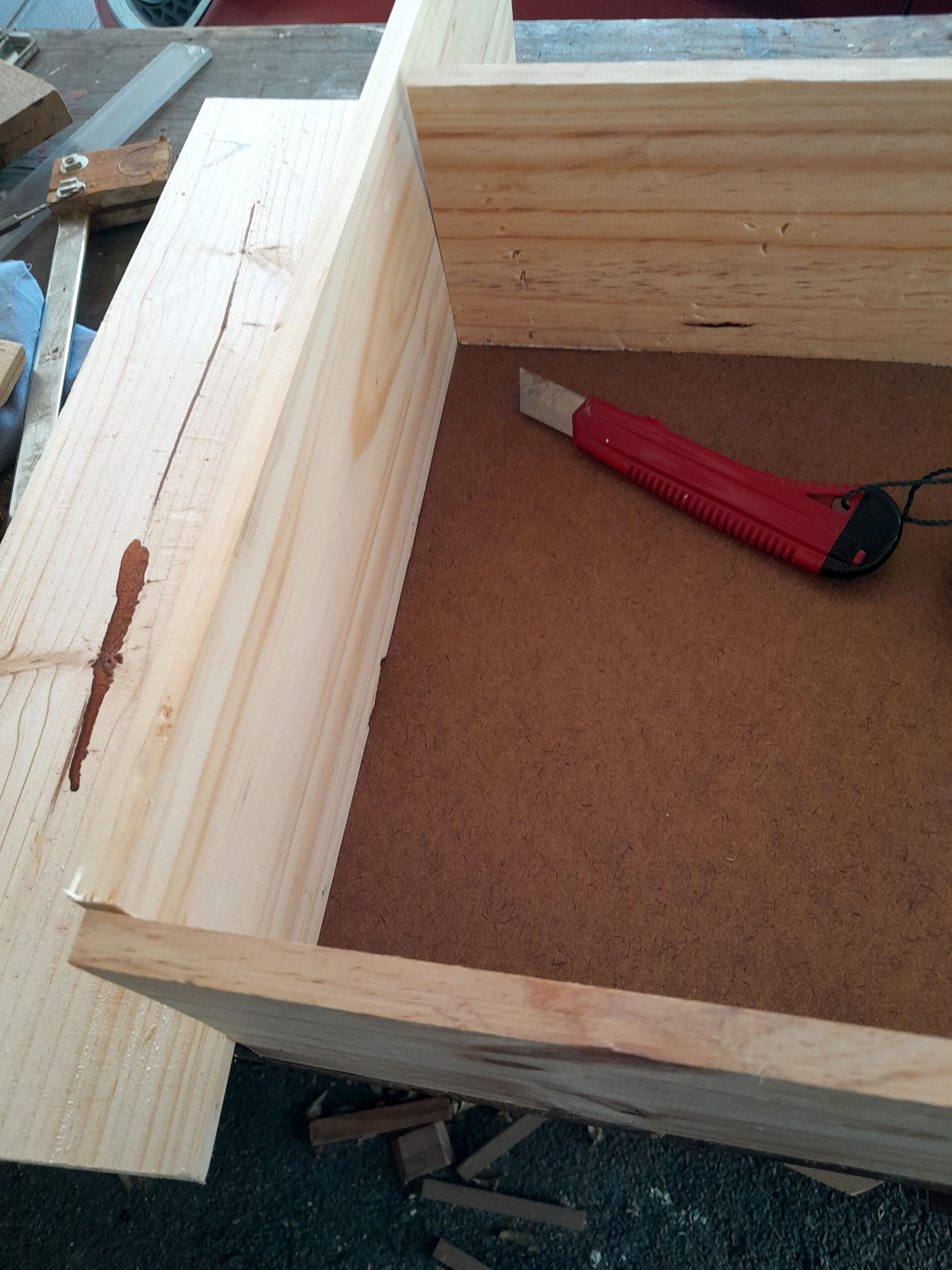
- I cut marked off and cut the sides in the same manner, and attached them to the base in the same manner.
- However, I used three 32mm panel pins per corner join to really secure each.
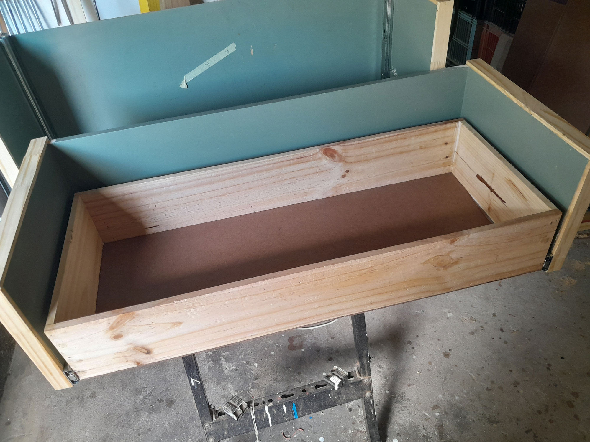
- Here is a dry fit of the new drawer in position in the carcass. Perfect fit.
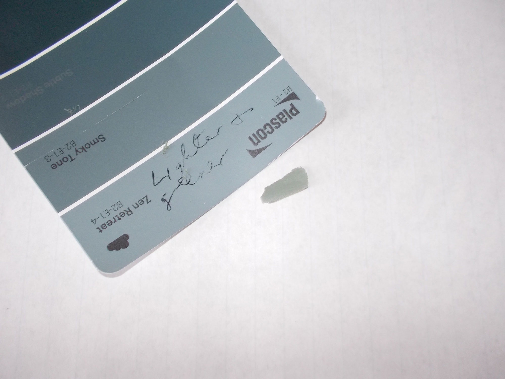
- I used a sliver of paint cut off the rear of the carcass as my colour swatch. A bit of choosing and discarding at my local Mica and we found the perfect match and I had a litre made up. That would be sufficient for the new drawers and touch-ups where the facades had lost paint thanks to scraping.
- After filling any marring depressions I sanded down the surfaces and applied the matching paint to the various surfaces that would be visible and fitted the drawer-side runners to the drawer. You will note that I applied paint to only the ends of the front panel… I did not have to paint the entire panel as this is the one to which the existing façade will be attached and would hide the bare wood. Then I fitted the drawer into the carcass to check for a full and free movement.
- It is as well to run the drawer fully out and fully in a few times. As you can see I used just 2 fingertips to do so, and could do so without any effort whatsoever.
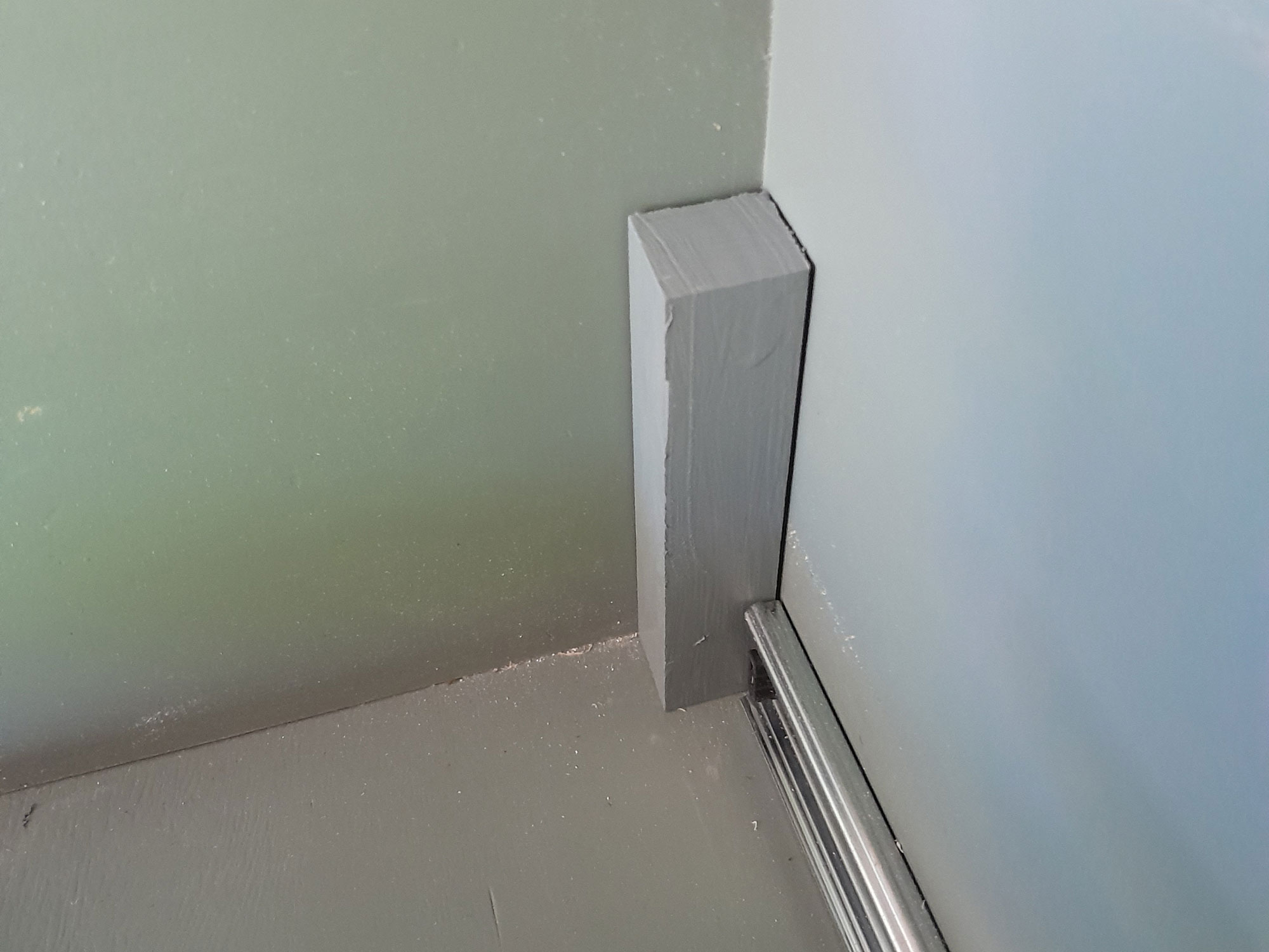
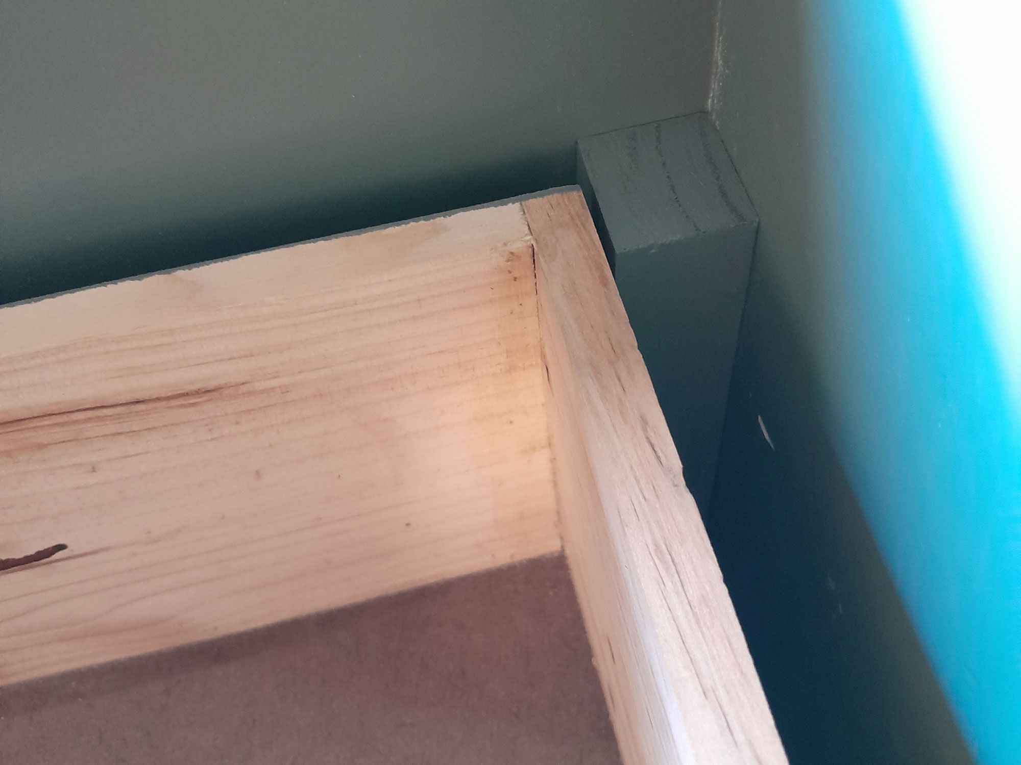
- And it opened and closed without any issues. I repeated the process for the second lower drawer to go into the other carcass – carcass ‘B’. It is important to ensure a bespoke fit for each drawer into its own carcass as there can be slight variations, and even a millimetre or so can be enough to cause problem. As the lower drawer is set forward 30mm (to make space for the upper shallower drawer, I decided to add a 32×32 section of wood to each corner, one side trimmed down to 30mm. Not only would this reinforce the rear corners on the drawer carcasses, but also prevent the lower drawer being pushed back so hard it might damage the runner end-stops.
- I used 6 of the 40mmx8 gauge screws to secure each 32×32 section of wood to each corner.
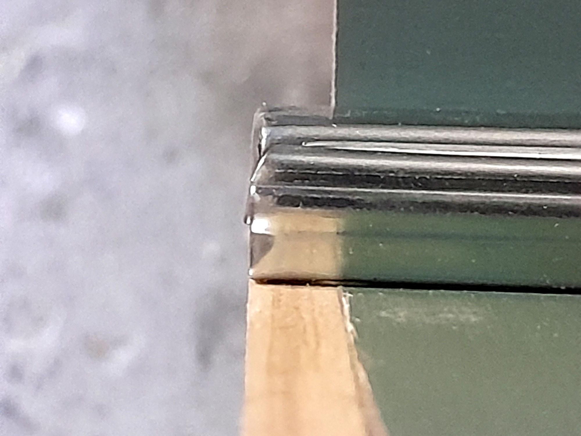
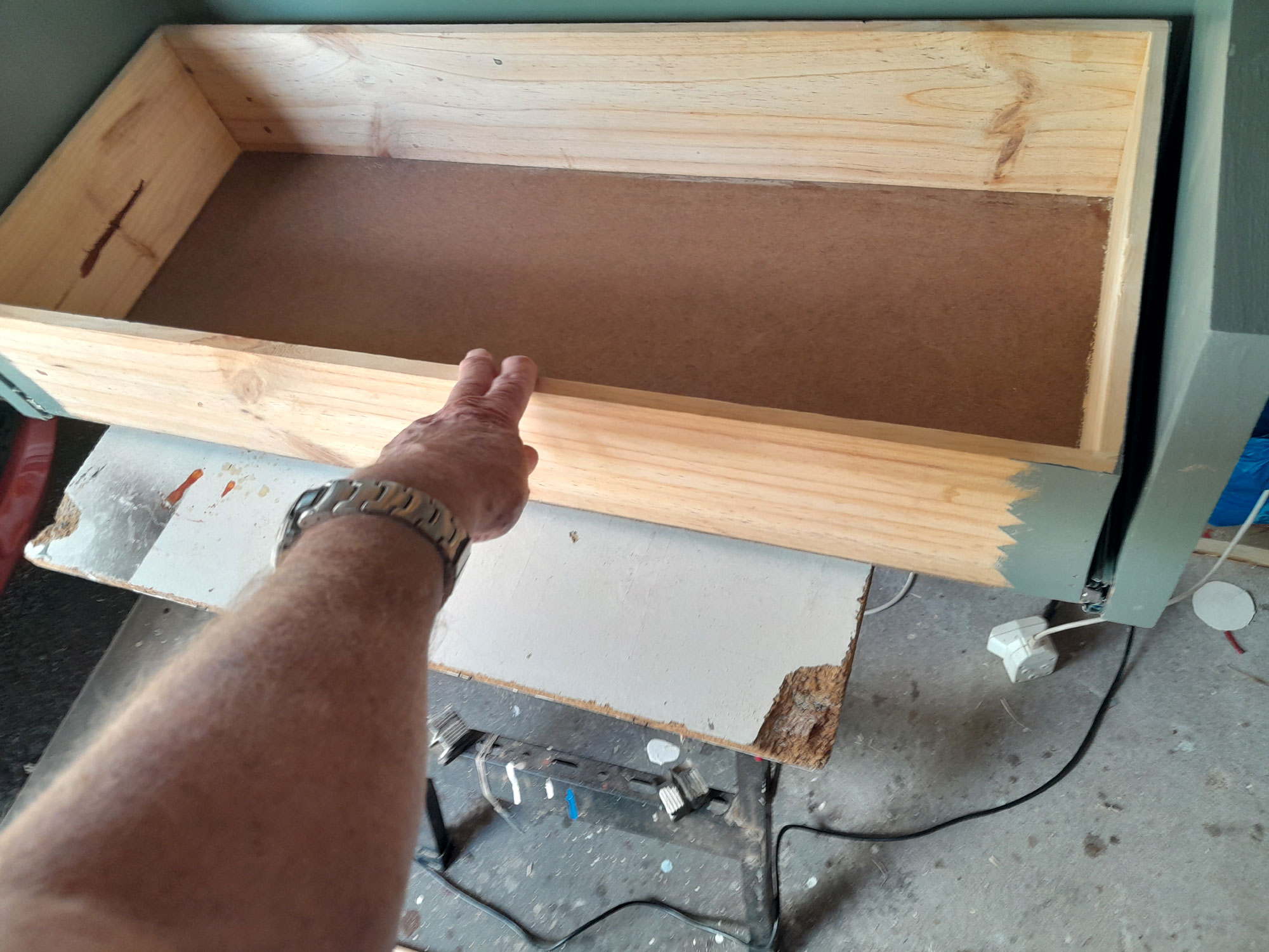
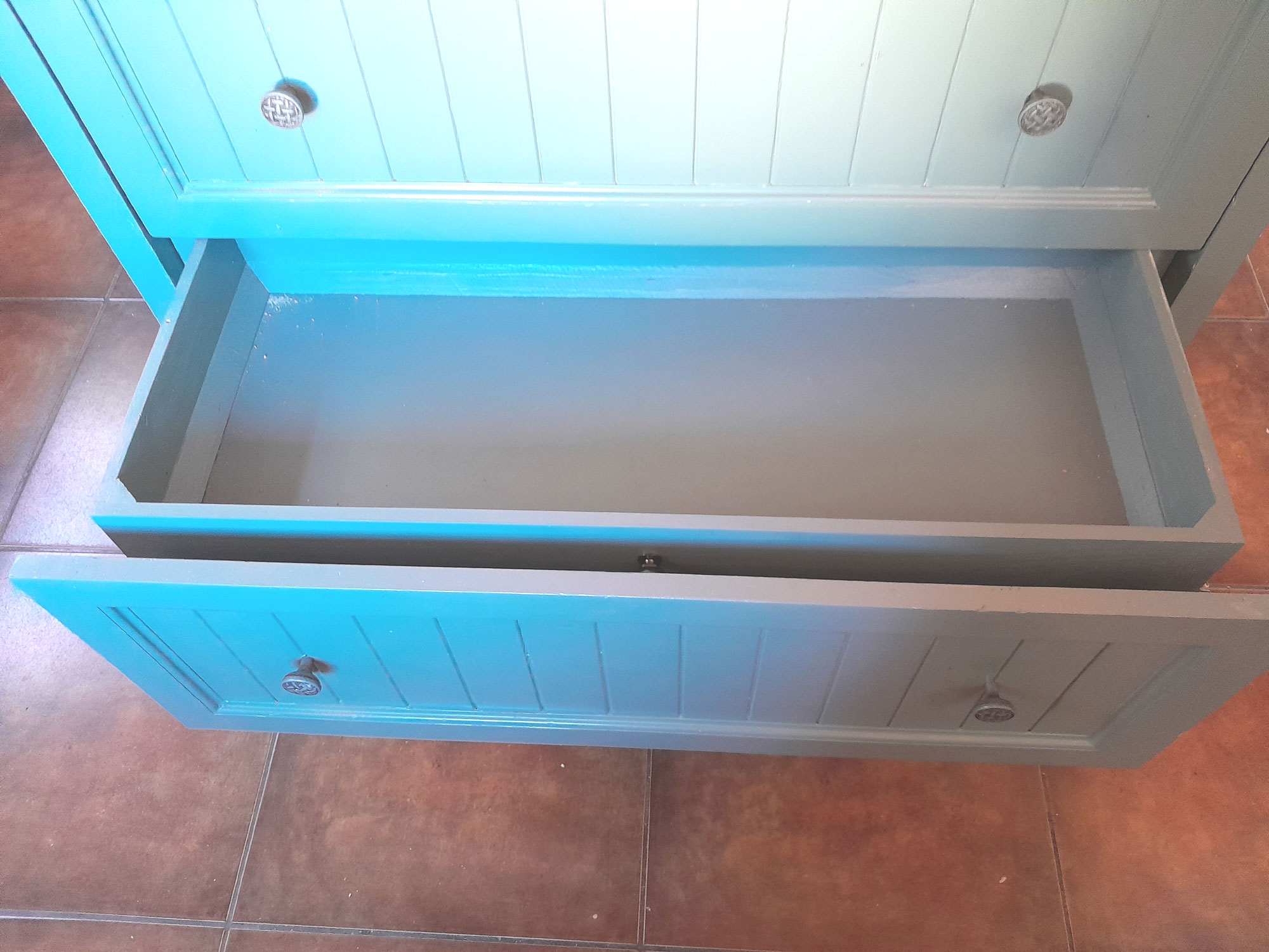
- This is how lower drawers come to rest when fully closed. Apropos the colour issue I mentioned above, note how the surface on the right looks bluish, while that at the rear is looks correct. Both surfaces are exactly the same colour.
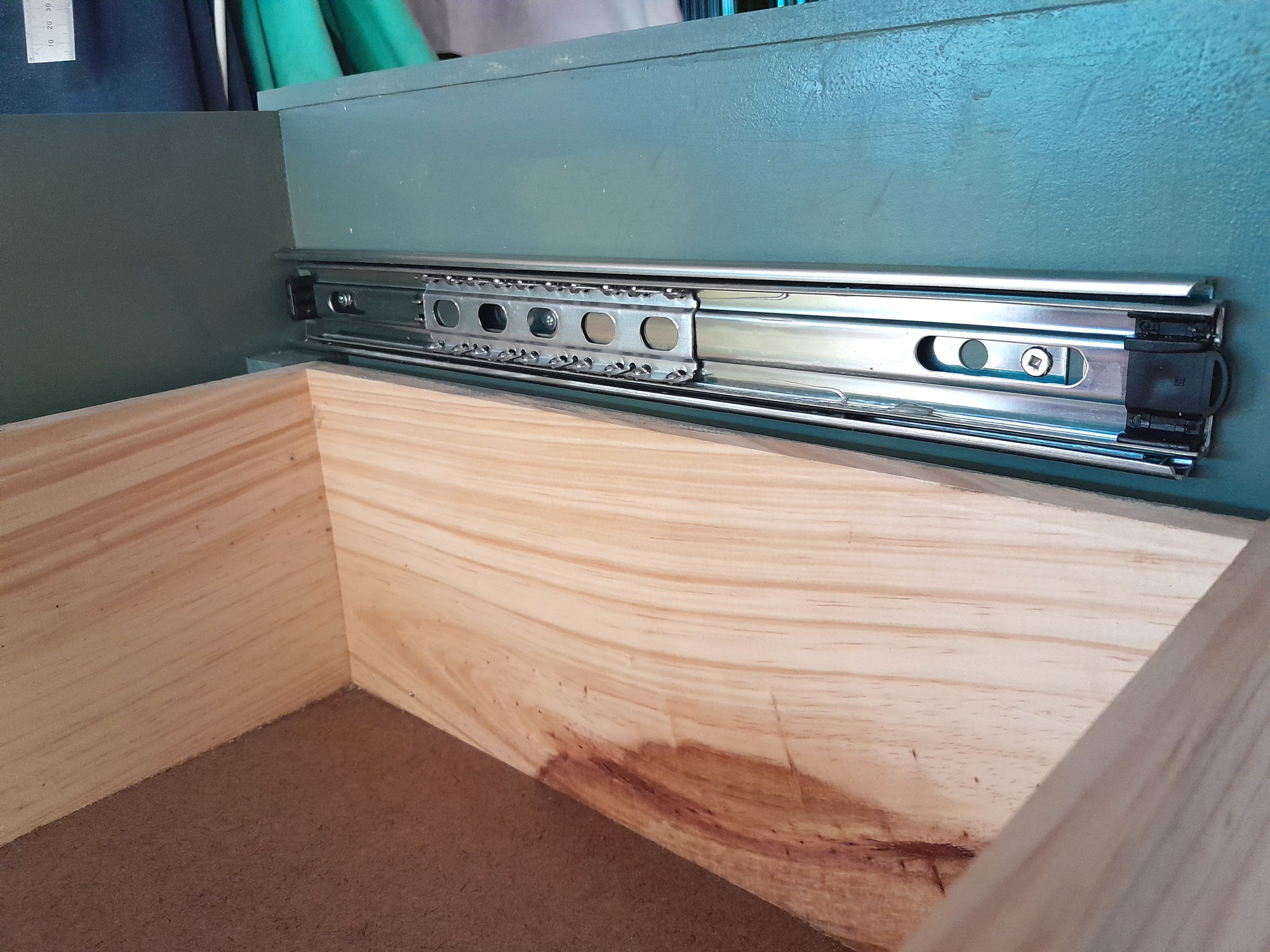
- I repeated the above processes to make the 2 upper drawers, this time using the 12x96mm wood for the drawer sides, but with exactly the same method of attachment in each case. This would ensure very solid drawers. Then I attached the runners to the sides of the drawer carcass. The best way to do this is to position the runner and then cut an offcut piece of wood to the desired width. Then use that as your “measuring” ruler. It will ensure that the spacing on all 4 runners will be identical.
- I used square head (Robertson) screws in attaching all the runners.
- And here is the fitting… this will ensure that the top of the upper drawer is level with, and not higher than the drawer carcass side, and there is also sufficient clearance between the 2 drawers.
- The gap between the 2 drawers is about 10mm in this case.
- Another view of the same set.
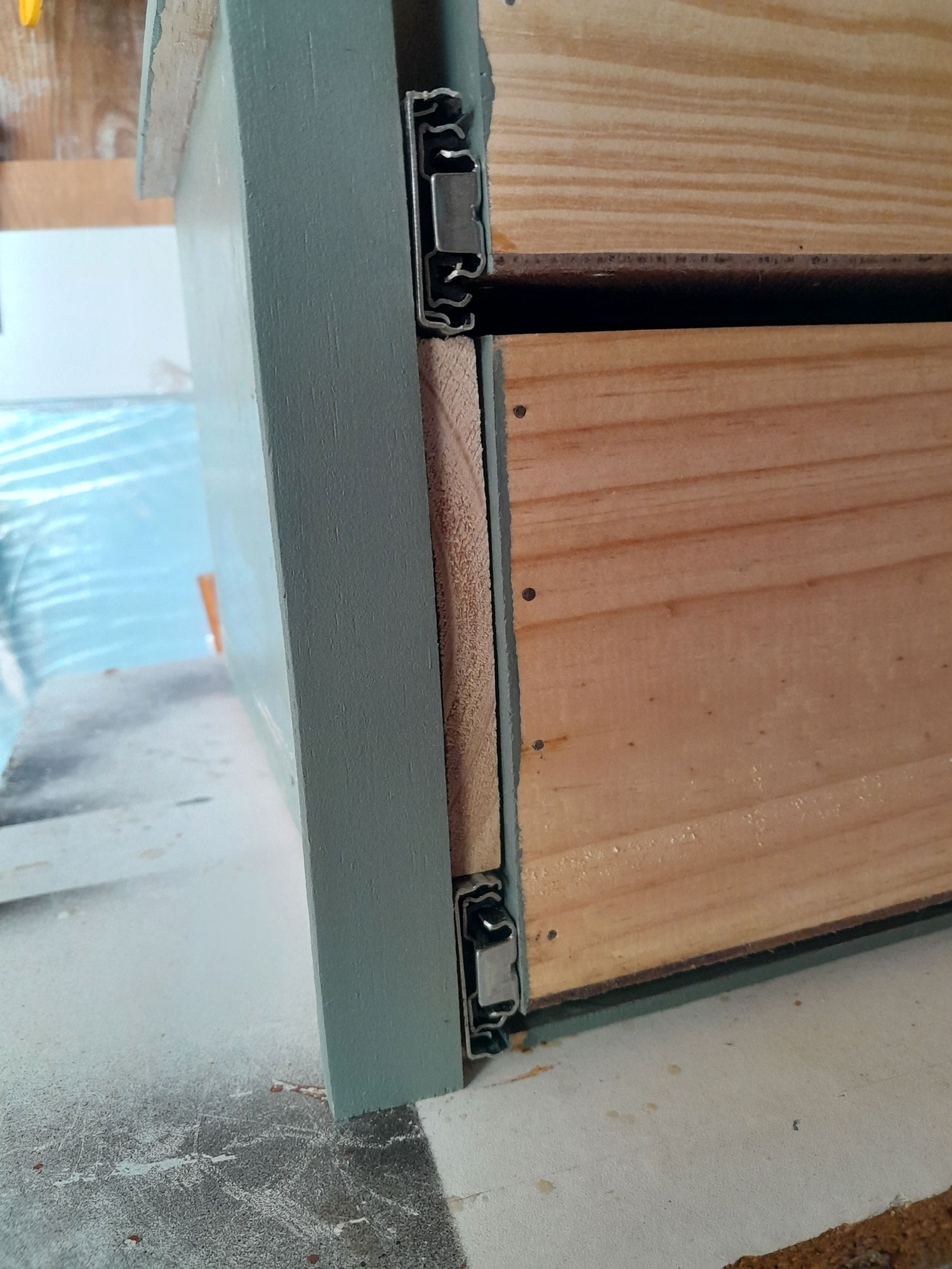
- Again, a checked a number of times to ensure both drawers could move freely, independently and without any collision or jamming.
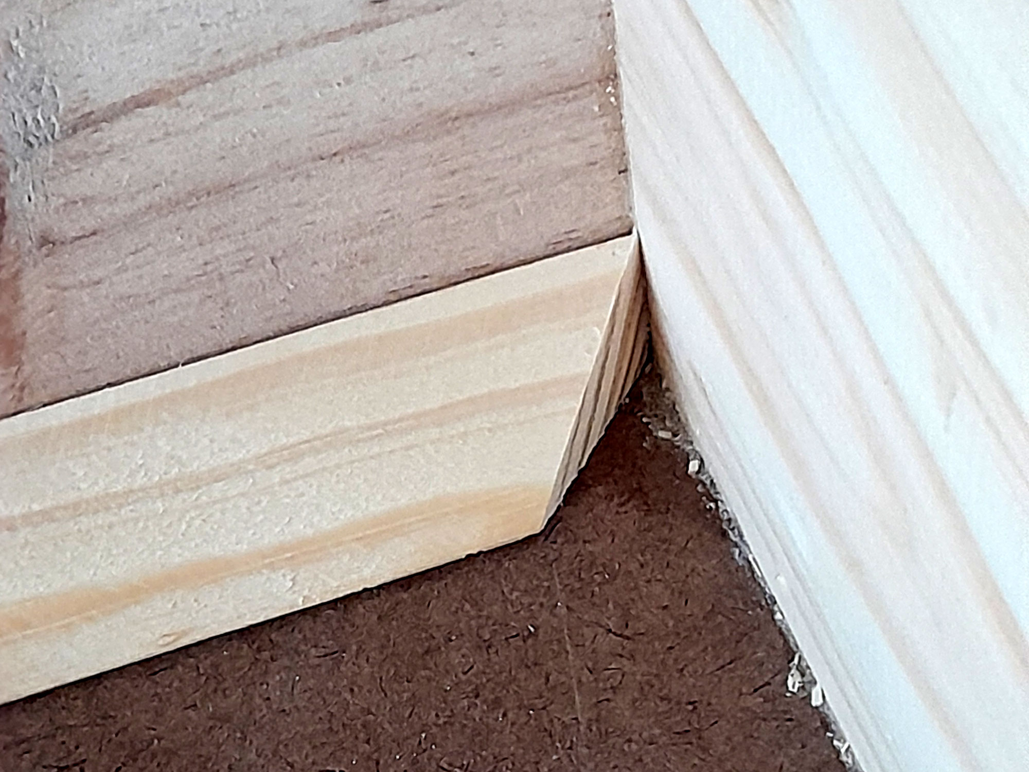
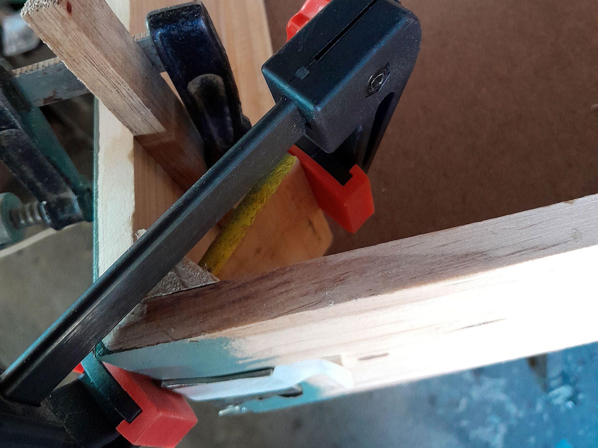
- The next step I took was to reinforce the join between the base and the sides on each drawer, using 22x22mm chamfer moulding, mitred at each end.
- A view of one of the mitred joints. Using the moulding ensured that there was a far larger glued surface to secure the base to the sides.
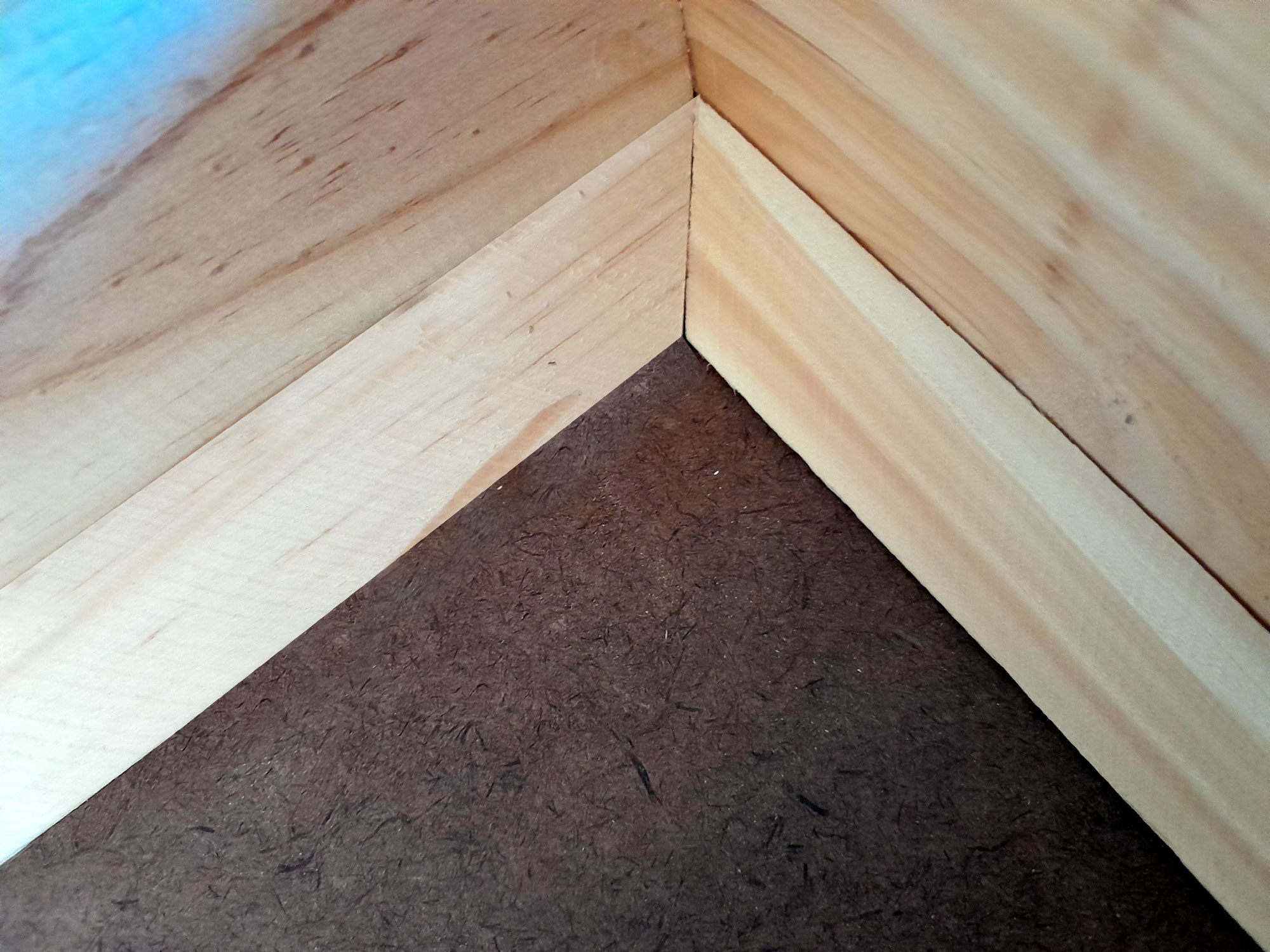
- I reinforced the corners as well, and did so using the same moulding, cut at a 45º angle as shown here.
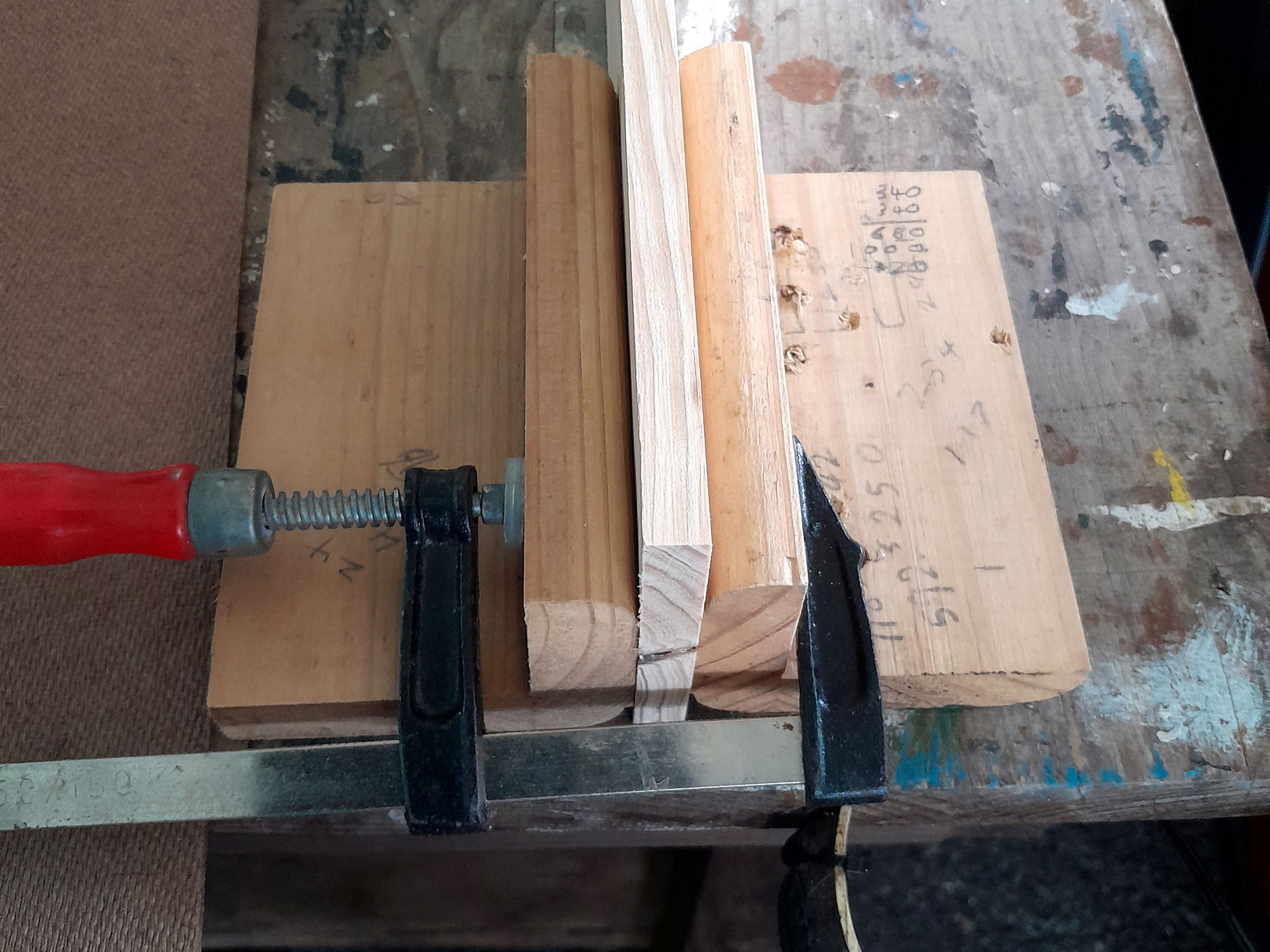
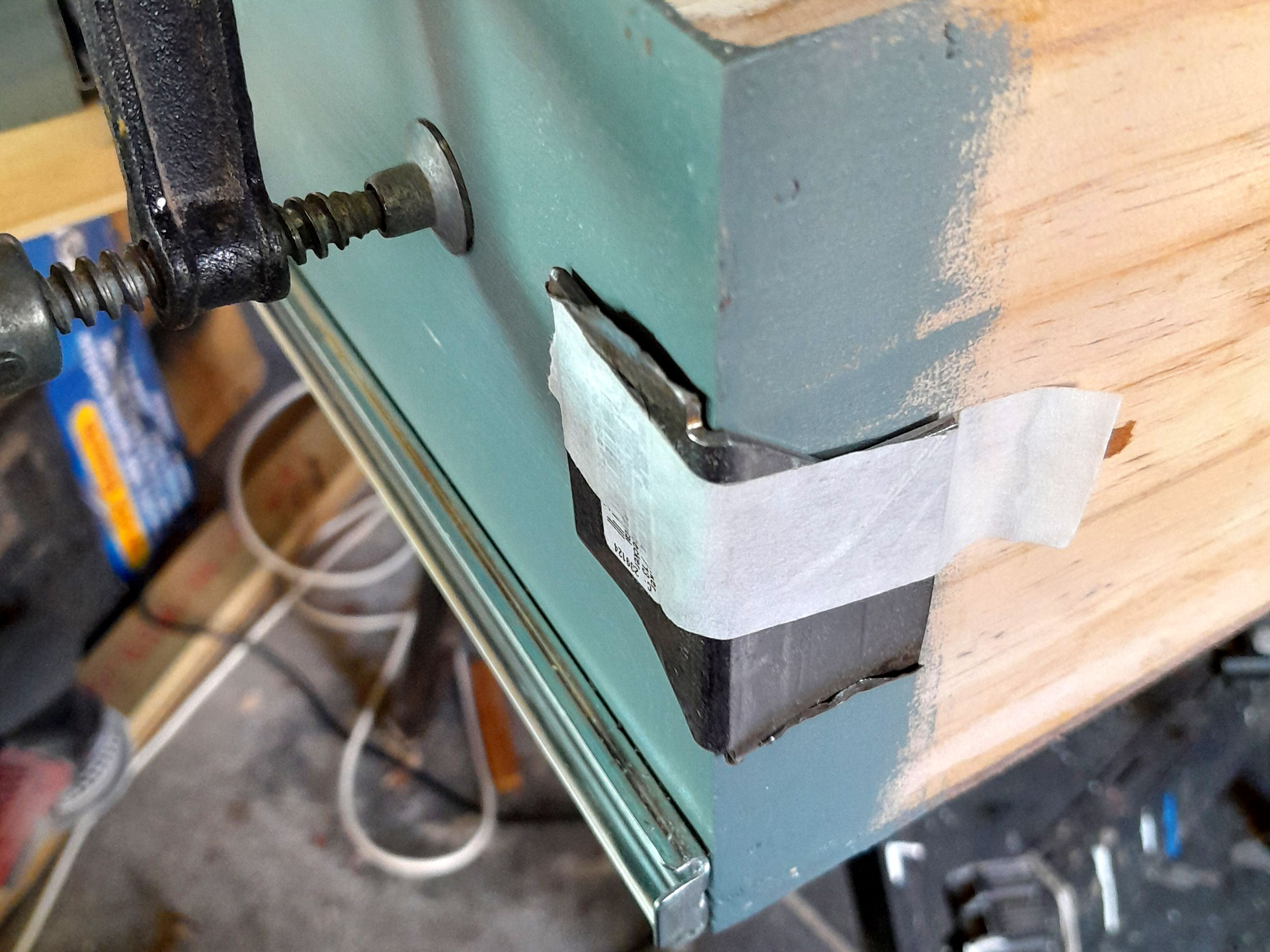
- Here’s a tip for you… To ensure the clamp used to secure the corner chamfer would not indent the corner of the drawer, I used a steel corner bracket on each… the tape is there just to hold it in place while I fitted the clamp in position.

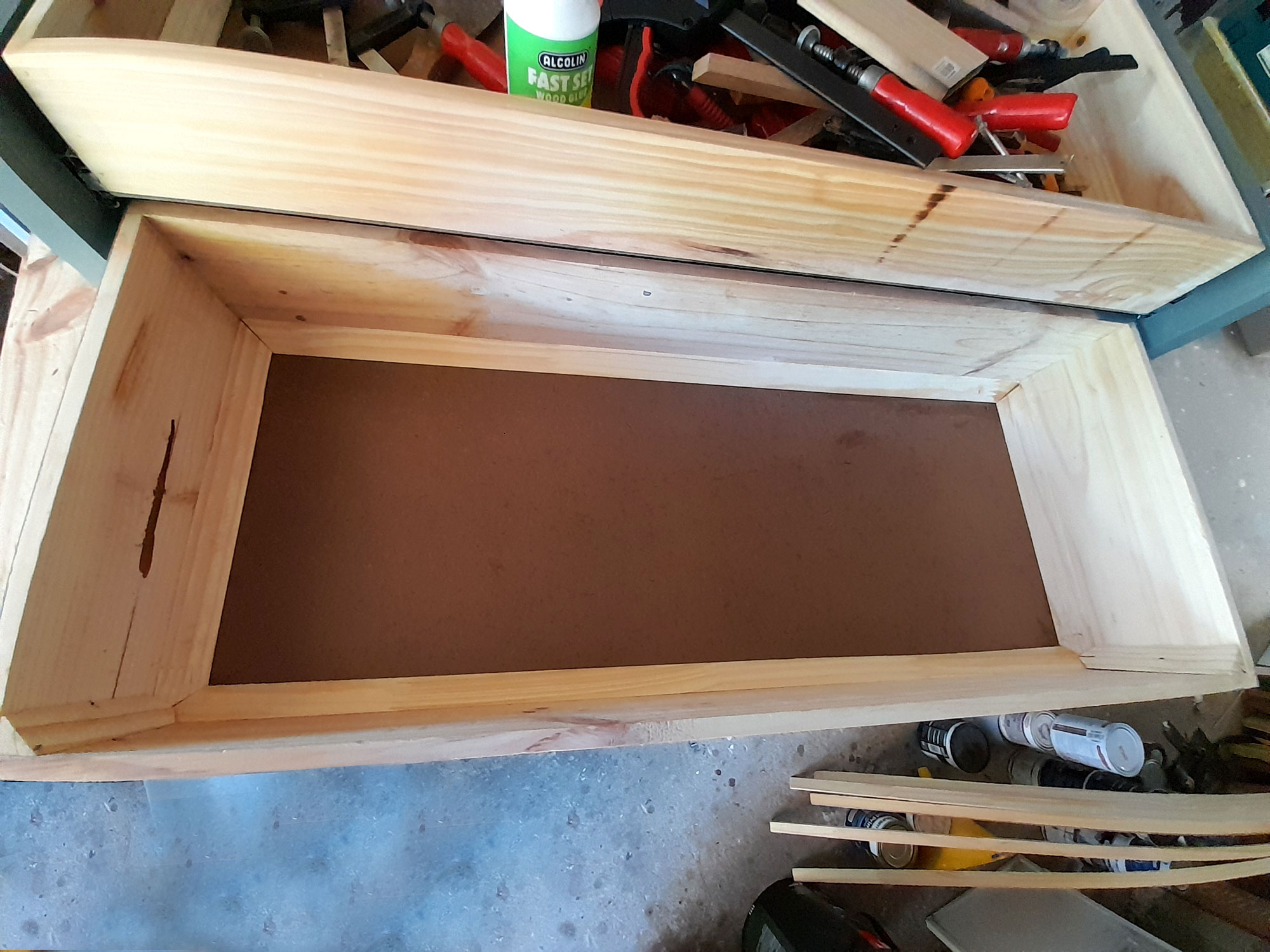
- There we are… just waiting for the glue to cure.
- Here is one completed lower drawer… solid as a rock!
- I painted the inside of the drawers and the moulding – I think anyway – doesn’t look bad at all.
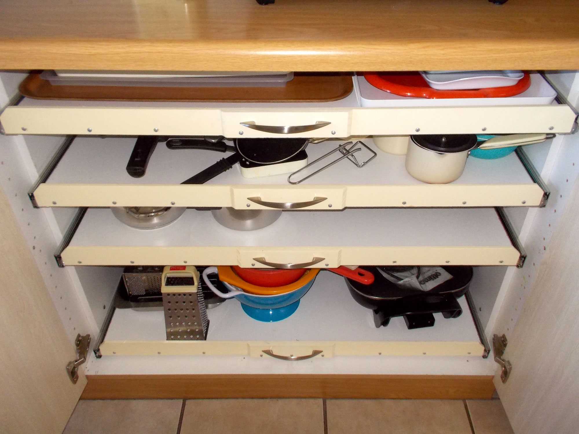
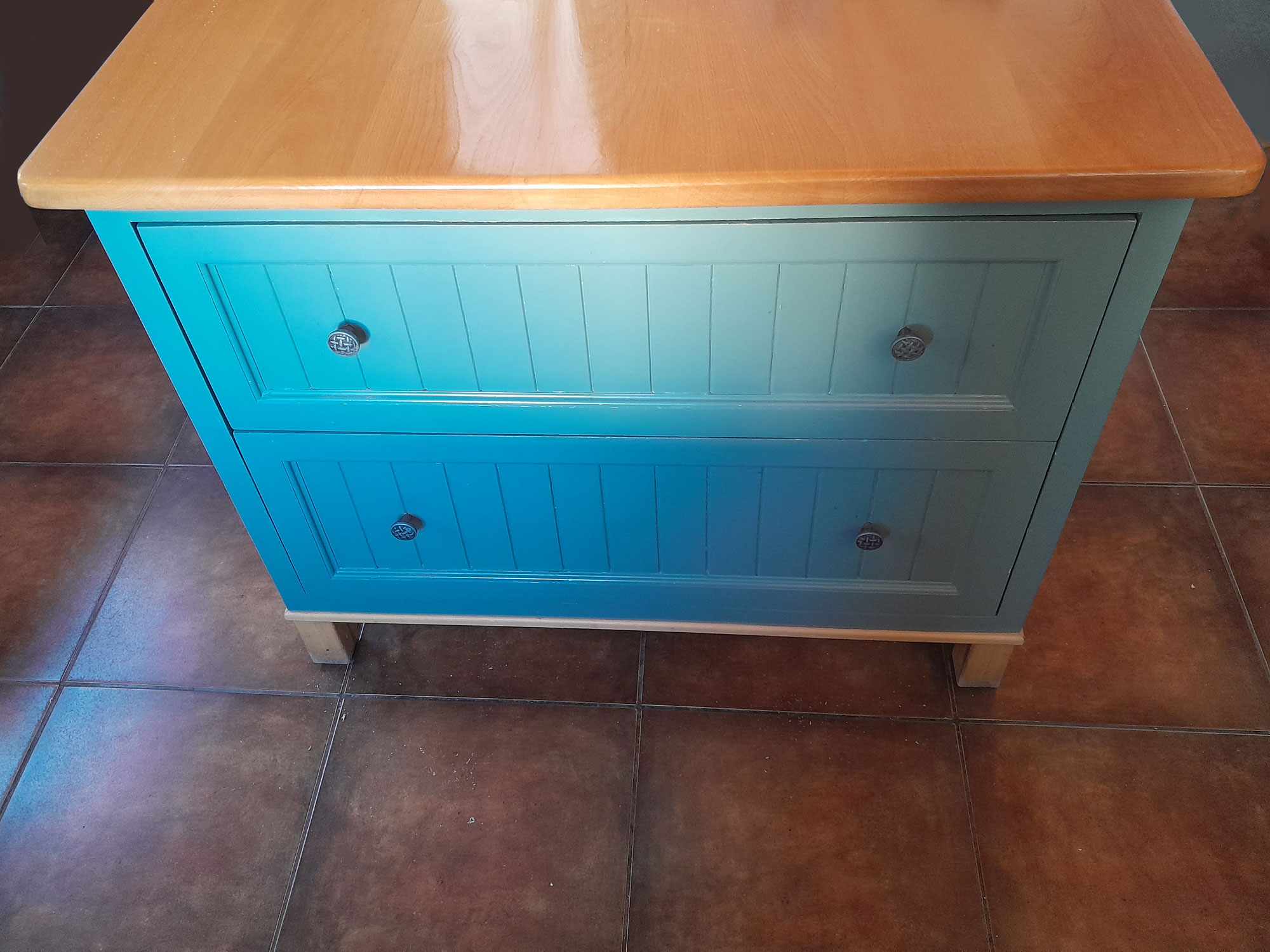
- Here are the 2 carcasses stacked as they will be fitted, and the 2 pairs of drawers and bottom carcass upper drawer in the fully out position. Just after this I attached the upper drawer knobs in the centre of each drawer front, and confirmed that the lower drawer in each carcass would close properly. Note please that this colour is the actual colour. That in the final shots is somewhat bluer, thanks to different light conditions.
- After some judicious sanding, as I had kept to very close tolerances, I fitted both carcasses into the kitchen cabinet, ensuring that they were fixed at the correct depth into the cabinet to allow the facades to be flush with the front of the cabinet. Then, using some offcuts of base hardboard, I positioned each façade and using the existing holes for their drawer knobs, drilled through the new lower drawer font panels and fixed the façade of each to its drawer. The façade is secured with the knob bolts only as I did not see any need to attach them with any additional screws.
- Here is a shot of the bottom drawer assembly open.
- And the final result… indistinguishable from the original, but now operating easily, with no scraping or jamming – and with 4 drawers instead of 2, and almost double the storage drawer area.

Panel:
These materials are available at Selected Mica Stores. To find your closest Mica and whether or not they stock the items required, please go to www.mica.co.za, find your store and call them. If your local Mica does not stock exactly what you need they will be able to order it for you or suggest an alternative product or a reputable source.
Project guide
TIME: little more than an hour, but spread over a couple of days
COST: +-R150, depending on the treatment you use and the cost of any replacement beading
Skill: 2
Assistant: No
Tools required:
Electrician’s scissors or wire stripper, small screwdriver